Nissan Sentra Service Manual: Component parts
Component Parts Location
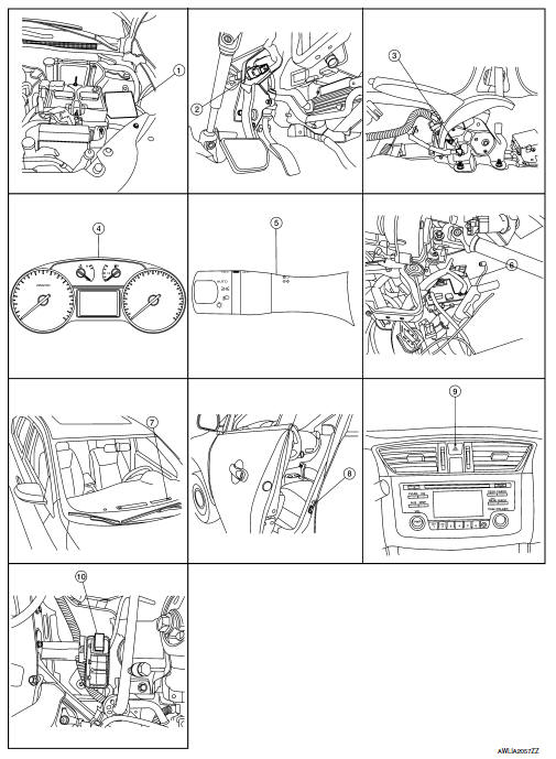
- IPDM E/R, (Headlamp high relay, Headlamp low relay, Taillamp relay and Front fog lamp relay (if equipped))
- Stop lamp switch
- Parking brake switch
- Combination meter
- Combination switch (lighting and turn signal switch)
- BCM (view with combination meter removed)
- Optical sensor
- Front door switch LH (Other doors similar)
- Hazard switch
- Daytime light relay (if equipped)
Component Description
| Part | Description |
| BCM | Controls the exterior lighting system. |
| Combination switch (Lighting & turn signal switch) | Refer to BCS-9, "COMBINATION SWITCH READING SYSTEM : System Description" (with Intelligent Key system) or BCS-80, "COMBINATION SWITCH READING SYSTEM : System Description" (without Intelligent Key system). |
| IPDM E/R | Controls the integrated relays and supplies voltage to the load according to the request from the BCM via CAN communication. |
| Stop lamp switch | Transmits power when the brake pedal is pressed to operate stop lamps. |
| Combination meter | Refer to MWI-8, "METER SYSTEM : System Description". |
| Daytime light relay (if equipped) | Sends power to the daytime lamp when operated by the IPDM E/R. |
| Front door switch LH/RH | Transmits the door open signal to the BCM. |
| Rear door switch LH/RH | |
| Optical sensor | Optical sensor converts the outside brightness (lux) to voltage and transmits the optical sensor signal to BCM to operate the autolight system. |
| Parking brake switch | Transmits the parking brake switch signal to the combination meter to operate the autolight system. |
| Hazard switch | Inputs the hazard switch signal to BCM. |

 System
Headlamp system
HEADLAMP SYSTEM : System Diagram
HEADLAMP SYSTEM : System Description
LOW BEAM OPERATION
When the lighting switch is in 2nd position, the BCM receives input
requesting the h ...
Other materials:
Precaution for Supplemental Restraint System (SRS) "AIR BAG" and "SEAT BELT
PRE-TENSIONER"
The supplemental restraint system such as “air bag” and “seat belt pre-tensioner”,
used along
with a front seat belt, helps to reduce the risk or severity of injury to the
driver and front passenger for certain
types of collision. Information necessary to service the system ...
Precaution for supplemental restraint system (SRS) "air bag" and "seat
belt pre-tensioner"
The Supplemental Restraint System such as “AIR BAG” and “SEAT BELT PRE-TENSIONER”,
used along
with a front seat belt, helps to reduce the risk or severity of injury to the
driver and front passenger for certain
types of collision. Information necessary to service the system ...
P0715 Input speed sensor A
DTC Logic
DTC DETECTION LOGIC
DTC
CONSULT screen terms
(Trouble diagnosis content)
DTC detection condition
Possible causes
P0715
INPUT SPEED SENSOR A
(Input/Turbine Speed Sensor
A Circuit)
The primary speed sensor value is less than
150 r ...
