Nissan Sentra Service Manual: System
Headlamp system
HEADLAMP SYSTEM : System Diagram
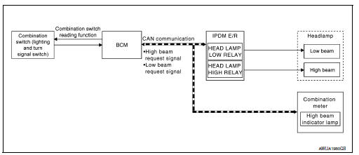
HEADLAMP SYSTEM : System Description
LOW BEAM OPERATION
When the lighting switch is in 2nd position, the BCM receives input requesting the headlamps to illuminate.
This input is communicated to the IPDM E/R across the CAN communication lines. The CPU of the IPDM E/R controls the headlamp low relay coil which supplies power to the low beam headlamps.
HIGH BEAM OPERATION/FLASH-TO-PASS OPERATION
With the lighting switch in the 2nd position and placed in HIGH position, the BCM receives input requesting the headlamp high beams to illuminate. The flash to pass feature can be used any time and also sends a signal to the BCM. This input is communicated to the IPDM E/R across the CAN communication lines. The CPU of the combination meter controls the ON/OFF status off the HIGH BEAM indicator. The CPU of the IPDM E/R controls the headlamp high relay coil which supplies power to the high beam headlamps.
The combination meter receives a high beam request signal (ON) through the CAN communication lines and turns the high beam indicator lamp ON.
EXTERIOR LAMP BATTERY SAVER CONTROL
With the combination switch (lighting and turn signal switch) in the 2nd position and the ignition switch is turned from ON or ACC to OFF, the battery saver feature is activated.
Under this condition, the headlamps remain illuminated for a period of time, unless the lighting switch position is changed. If the lighting switch position is changed, then the headlamps are turned off.
Auto light system
Auto light system : system diagram
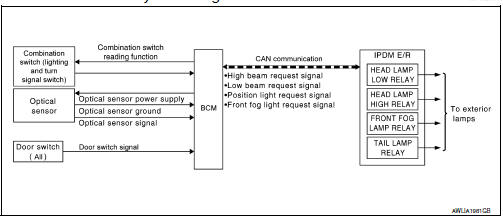
Auto light system : system description
- BCM (Body Control Module) controls auto light operation according to signals from optical sensor, lighting switch and ignition switch.
- IPDM E/R (Intelligent Power Distribution Module Engine Room) operates parking, license plate, tail, front fog lamps and headlamps according to CAN communication signals from BCM.
- Optical sensor detects ambient brightness of 800 to 2,500 lux. And optical sensor converts light (lux) to voltage, then sends the optical sensor signal to BCM.
OUTLINE
The auto light control system has an optical sensor that detects outside brightness.
When the lighting switch is in AUTO position, it automatically turns ON/OFF the parking, license plate, tail, front fog lamps and headlamps in accordance with the ambient light. Sensitivity can be adjusted. For the details of the setting, Refer to EXL-19, "HEADLAMP : CONSULT Function (BCM - HEAD LAMP)".
Daytime running light system
Daytime running light system : system diagram
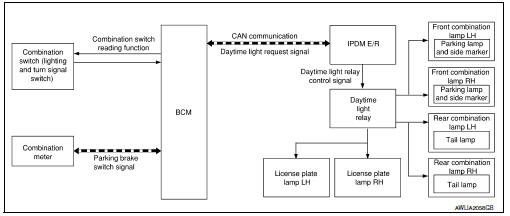
Daytime running light system : system description
System Description
The daytime light system is equipped with a daytime light control that activates the daytime lights when the engine is operating. If the parking brake is applied, the daytime lights will turn OFF. The daytime lights will turn ON when the parking brake is released.
OPERATION
The BCM monitors inputs from the parking brake switch and the combination switch (lighting and turn signal switch) to determine when to operate the daytime light system. The BCM sends a daytime light request to the IPDM E/R via the CAN communication lines. The IPDM E/R grounds the daytime light relay which in turn, provides power to the daytime lights.
Front fog lamp system
FRONT FOG LAMP SYSTEM : System Diagram
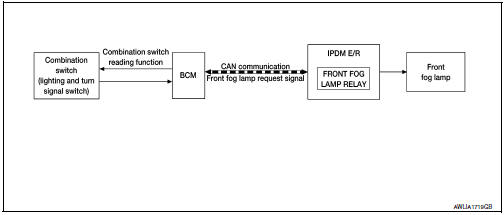
FRONT FOG LAMP SYSTEM : System Description
The front fog lamps are activated with the combination switch (lighting and turn signal switch). The lighting switch signal to the BCM is monitored with the BCM combination switch reading function. When the fog lamps are turned ON with the lighting switch, the BCM sends a front fog lamp request signal via CAN communication lines to the IPDM E/R. The IPDM E/R grounds the front fog lamp relay coil to activate the front fog lamps.
FRONT FOG LAMP OPERATION
When the lighting switch is in front fog lamp ON position and also in 1st or 2nd position or AUTO position (headlamp is ON), the BCM detects FR FOG ON and the HEAD LAMP 1, 2 ON or the AUTO LIGHT ON. The BCM sends a front fog lamp request ON signal via the CAN communication lines to the IPDM E/R. The IPDM E/R then turns ON the front fog lamp relay sending power to the front fog lamps.
Turn signal and hazard warning lamps.
Turn signal and hazard warning lamps : system diagram
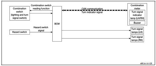
Turn signal and hazard warning lamps : system description
TURN SIGNAL OPERATION
When the combination switch (lighting and turn signal switch) is in LH or RH turn position with the ignition switch in the ON position, the BCM receives input requesting the turn RH or turn LH lamps to illuminate. The BCM controls the turn signal power to the respective turn signal lamp. The BCM also sends a turn indicator signal ON request via the CAN communication lines to the combination meter. The combination meter then activates the appropriate turn signal indicator and audible buzzer.
HAZARD LAMP OPERATION
When the hazard switch is in the ON position, the BCM receives input requesting the hazard lamps illuminate.
The BCM controls the turn signal power to both the LH and RH turn signal lamps. The BCM sends a hazard indicator signal ON request via the CAN communication lines to the combination meter. The combination meter then activates both the LH and RH turn signal indicators and audible buzzer.
Parking, license plate and tail lamps
Parking, license plate and tail lamps : system diagram
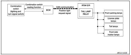
PARKING, LICENSE PLATE AND TAIL LAMPS OPERATION
When the lighting switch is in 1st or 2nd position, BCM detects the LIGHTING SWITCH 1st or 2nd POSITION ON. The BCM sends a parking light ON request via the CAN communication lines to the IPDM E/R. The IPDM E/R then activates the tail lamp relay which sends power to the parking and instrument illumination circuits.
EXTERIOR LAMP BATTERY SAVER CONTROL
With the combination switch (lighting and turn signal switch) in the 1st or 2nd position and the ignition switch is turned from ON or ACC to OFF, the battery saver feature is activated.
Under this condition, the exterior lamps remain illuminated for a period of time unless the lighting switch position is changed. If the lighting switch position is changed, then the exterior lamps are turned off.
Combination switch reading system
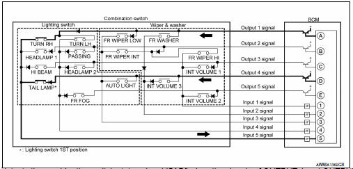
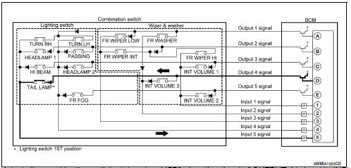
Combination switch reading system : system diagram (with intelligent key system)
Combination switch reading system : system description (with intelligent key system)
OUTLINE
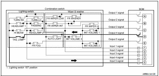
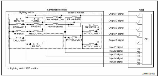
- BCM reads the status of the combination switch (light, turn signal, wiper and washer) and recognizes the status of each switch.
- BCM has a combination of 5 output terminals (OUTPUT 1 - 5) and 5 input terminals (INPUT 1 - 5). It reads a maximum of 20 switch states.
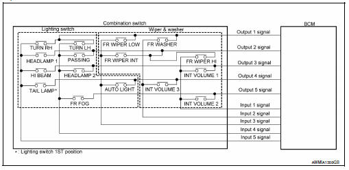
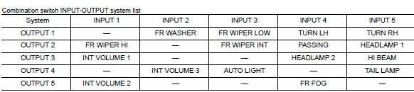
COMBINATION SWITCH MATRIX
Combination switch circuit
COMBINATION SWITCH READING FUNCTION
Description
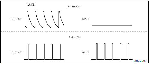
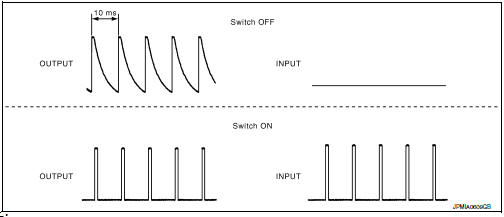
- BCM reads the status of the combination switch at 10 ms intervals normally.
NOTE:
BCM reads the status of the combination switch at 60 ms intervals when BCM is controlled at low power consumption control mode.
- BCM operates as follows and judges the status of the combination switch.
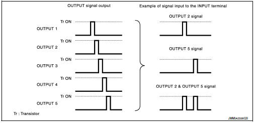
- It operates the transistor on OUTPUT side in the following order: OUTPUT 1 → 2 → 3 → 4 → 5, and outputs voltage waveform.
- The voltage waveform of OUTPUT corresponding to the formed circuit is input into the interface on INPUT side if any (1 or more) switches are ON.
- It reads this change of the voltage as the status signal of the combination switch.
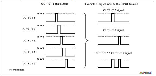
Operation Example
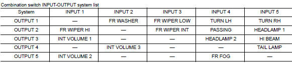
In the following operation example, the combination of the status signals of the combination switch is replaced as follows: INPUT 1 - 5 to “1 - 5” and OUTPUT 1 - 5 to “A - E”.
Example 1: When a switch (TAIL LAMP) is turned ON
- The circuit between OUTPUT 4 and INPUT 5 is formed when the TAIL LAMP switch is turned ON.
- BCM detects the combination switch status signal “5D” when the signal of OUTPUT 4 is input to INPUT 5.
- BCM judges that the TAIL LAMP switch is ON when the signal “5D” is detected.
Example 2: When some switches (TURN RH, TAIL LAMP) are turned ON
- The circuits between OUTPUT 1 and INPUT 5 and between OUTPUT 4 and INPUT 5 are formed when the TURN RH switch and TAIL LAMP switch are turned ON.
- BCM detects the combination switch status signal “5AD” when the signals of OUTPUT 1 and OUTPUT 4 are input to INPUT 5.
- BCM judges that the TURN RH switch and TAIL LAMP switch are ON when the signal “5AD” is detected.
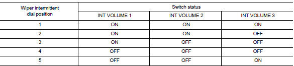
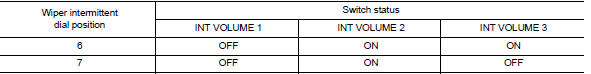
Wiper intermittent dial position
BCM judges the wiper intermittent dial 1 - 7 by the status of INT VOLUME 1, 2 and 3 switches.
Note:
For details of wiper intermittent dial position, refer to WW-8, "System Description".
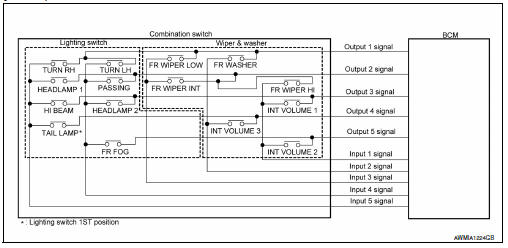
Combination switch reading system : system diagram (without intelligent key system)
Combination switch reading system : system description (without intelligent key system)
OUTLINE
- BCM reads the status of the combination switch (light, turn signal, wiper and washer) and recognizes the status of each switch.
- BCM has a combination of 5 output terminals (OUTPUT 1 - 5) and 5 input terminals (INPUT 1 - 5). It reads a maximum of 20 switch states.
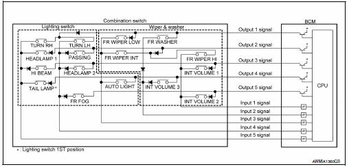
Combination switch matrix
Combination switch circuit
Combination switch reading function
Description
- Bcm reads the status of the combination switch at 10 ms intervals normally.
Note:
Bcm reads the status of the combination switch at 60 ms intervals when bcm is controlled at low power consumption control mode.
Bcm operates as follows and judges the status of the combination switch.
- It operates the transistor on output side in the following order: output 1 ƒ¸ 2 ƒ¸ 3 ƒ¸ 4 ƒ¸ 5, and outputs voltage waveform.
- The voltage waveform of output corresponding to the formed circuit is input into the interface on input side if any (1 or more) switches are on.
- It reads this change of the voltage as the status signal of the combination switch.
Operation example
In the following operation example, the combination of the status signals of the combination switch is replaced as follows: input 1 - 5 to “1 - 5” and output 1 - 5 to “a - e”.
Example 1: when a switch (tail lamp) is turned on
- The circuit between OUTPUT 4 and INPUT 5 is formed when the TAIL LAMP switch is turned ON.
- Bcm detects the combination switch status signal “5d” when the signal of output 4 is input to input 5.
- Bcm judges that the tail lamp switch is on when the signal “5d” is detected.
Example 2: when some switches (turn rh, tail lamp) are turned on
The circuits between OUTPUT 1 and INPUT 5 and between OUTPUT 4 and INPUT 5 are formed when the TURN RH switch and TAIL LAMP switch are turned ON.
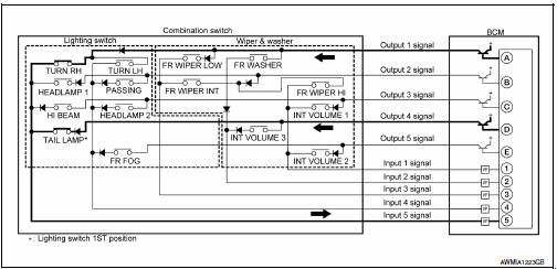
- Bcm detects the combination switch status signal “5ad” when the signals of output 1 and output 4 are input to input 5.
- Bcm judges that the turn rh switch and tail lamp switch are on when the signal “5ad” is detected.
 Component parts
Component Parts Location
IPDM E/R, (Headlamp high relay,
Headlamp low relay, Taillamp relay
and Front fog lamp relay (if equipped))
Stop lamp switch
Parking brake switch
Combination ...
 Diagnosis system (bcm) (with intelligent key system)
Common item
Common item : consult function (bcm - common item)
Application item
Consult performs the following functions via can communication with bcm.
Direct diagnostic mode
Descriptio ...
Other materials:
Pandora® audio (if so equipped)
The vehicle’s audio system is capable of playing
audio streaming through a compatible, USBconnected
audio device using the Pandora® music
service.
Connecting a device for use with
Pandora® audio
Devices capable of streaming Pandora® audio
can be connected to the vehicle’s audio system
...
Seat belt maintenance
To clean the seat belt webbing, apply a
mild soap solution or any solution recommended
for cleaning upholstery or carpet.
Then wipe with a cloth and allow the seat
belts to dry in the shade. Do not allow the
seat belts to retract until they are completely
dry.
If dirt builds up in t ...
Ignition coil
Exploded View
Ignition coil
Spark plug
Rocker cover
Removal and Installation
REMOVAL
Remove the engine room cover. Refer to EM-24, "Exploded View".
Disconnect the harness connector from the ignition coil.
Remove the ignition coil.
CAUTION:
Do not drop or shock i ...
