Nissan Sentra Service Manual: P0715 Input speed sensor A
DTC Logic
DTC DETECTION LOGIC
|
DTC |
CONSULT screen terms (Trouble diagnosis content) |
DTC detection condition |
Possible causes |
| P0715 | INPUT SPEED SENSOR A (Input/Turbine Speed Sensor A Circuit) | The primary speed sensor value is less than
150 rpm continuously for 5 seconds or more
under the following diagnosis conditions: Diagnosis conditions
|
|
| The primary speed sensor value is 240 rpm or
less continuously for 500 msec or more under
the following diagnosis conditions: Diagnosis conditions
|
DTC CONFIRMATION PROCEDURE
CAUTION:
Be careful of the driving speed.
1.PREPARATION BEFORE WORK
If another “DTC CONFIRMATION PROCEDURE” occurs just before, turn ignition switch OFF and wait for at least 10 seconds, then perform the next test.
>> GO TO 2.
2.CHECK DTC DETECTION
- Start the engine.
- Drive the vehicle.
- Maintain the following conditions for 10 seconds or more.
Selector lever : “L” POSITION
Vehicle speed : 40 km/h (25 MPH) or more
- Stop the vehicle.
- Check the first trip DTC.
Is “P0715” detected? YES >> Go to TM-178, "Diagnosis Procedure".
NO >> INSPECTION END
Diagnosis Procedure
1.CHECK PRIMARY SPEED SENSOR POWER CIRCUIT
- Turn ignition switch OFF.
- Disconnect primary speed sensor connector.
- Turn ignition switch ON.
- Check voltage between primary speed sensor harness connector terminal and ground.
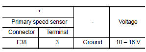
Is the check result normal? YES >> GO TO 2.
NO >> GO TO 6.
2.CHECK PRIMARY SPEED SENSOR GROUND CIRCUIT
Check continuity between primary speed sensor harness connector terminal and ground.
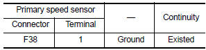
Is the check result normal? YES >> GO TO 3.
NO >> Repair or replace malfunctioning parts
3.CHECK CIRCUIT BETWEEN PRIMARY SPEED SENSOR AND TCM (PART 1)
- Turn ignition switch OFF.
- Disconnect TCM connector.
- Check continuity between primary speed sensor harness connector terminal and TCM harness connector terminal.
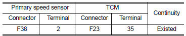
Is the check result normal? YES >> GO TO 4.
NO >> Repair or replace malfunctioning parts.
4.CHECK CIRCUIT BETWEEN PRIMARY SPEED SENSOR AND TCM (PART 2)
Check continuity between primary speed sensor harness connector terminal and ground.
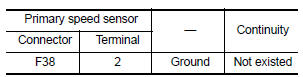
Is the check result normal? YES >> GO TO 5.
NO >> Repair or replace malfunctioning parts.
5.Check TCM Input signals
- Connect all of disconnected connectors.
- Lift the vehicle.
- Start the engine.
- Check frequency of primary speed sensor.
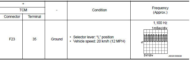
Is the check result normal? YES >> Check intermittent incident. Refer to GI-39, "Intermittent Incident".
NO >> Replace primary speed sensor. Refer to TM-268, "Removal and Installation".
6.DETECT MALFUNCTIONING ITEMS
Check the following items:
- Harness open circuit or short circuit between the ignition switch and IPDM E/R. Refer to PG-20, "Wiring Diagram — Ignition Power Supply —".
- Harness open circuit or short circuit between IPDM E/R and primary speed sensor.
- 10A fuse (No.45, IPDM E/R). Refer to PG-49, "IPDM E/R Terminal Arrangement".
- IPDM E/R
Is the check result normal? YES >> Check intermittent incident. Refer to GI-39, "Intermittent Incident".
NO >> Repair or replace malfunctioning parts.
 P0713 Transmission fluid temperature sensor A
DTC Logic
DTC DETECTION LOGIC
DTC
CONSULT screen terms
(Trouble diagnosis content)
DTC detection condition
Possible causes
P0713
FLUID TEMP SENSOR A
(Transmission ...
 P0720 Output speed sensor
DTC Logic
DTC DETECTION LOGIC
DTC
CONSULT screen terms
(Trouble diagnosis content)
DTC detection condition
Possible causes
P0720
OUTPUT SPEED SENSOR
(Output Speed ...
Other materials:
OIL PAN
Exploded View
Transaxle assembly
Oil pan gasket
Magnet
Oil pan
Overflow tube
Drain plug gasket
Drain plug
Oil pan fitting bolt
: Always replace after every
disassembly.
: NВ·m (kg-m, ft-lb)
: NВ·m (kg-m, it-lb)
Removal and Installation
REMOVAL
Remove the en ...
Rear drum brake
Brake Burnishing
CAUTION:
Burnish contact surfaces between brake drum and brake lining
according to the following procedure
after refinishing or replacing brake drum, or if a soft pedal occurs at very
low mileage.
Be careful of vehicle speed because the brake does not operate
firml ...
Spark plugs
Replacing spark plugs
WARNINGBe sure the engine and ignition switch are
off and that the parking brake is engaged
securely.
CAUTION
Be sure to use the correct socket to remove
the spark plugs. An incorrect socket
can damage the spark plugs.
Platinum-tipped spark plugs (ex ...
