Nissan Sentra Service Manual: Dtc/circuit diagnosis
U1000 can comm circuit
Description
Refer to LAN-7, "CAN COMMUNICATION SYSTEM : System Description".
Dtc logic
DTC DETECTION LOGIC
| CONSULT Display | DTC Detection Condition | Possible Cause |
| CAN COMM CIRCUIT [U1000] | When IPDM E/R cannot communicate with CAN communication signal continuously for 2 seconds or more | In CAN communication system, any item (or items) of
the following listed below is malfunctioning.
|
Diagnosis procedure
1. PERFORM SELF DIAGNOSTIC RESULT
- Turn ignition switch ON and wait for 2 second or more.
- Check “SELF-DIAG RESULTS” of IPDM E/R.
Is “CAN COMM CIRCUIT” displayed? YES >> Refer to LAN-16, "Trouble Diagnosis Flow Chart".
NO >> Refer to GI-39, "Intermittent Incident".
B2098 ignition relay on stuck
Dtc logic
DTC DETECTION LOGIC
| CONSULT Display | DTC Detection Condition | Possible Cause |
| IGN RELAY ON [B2098] | The ignition relay ON is detected for 1 second at ignition switch OFF (CPU monitors the status at the contact and excitation coil circuits of the ignition relay inside it) | IPDM E/R |
DTC CONFIRMATION PROCEDURE
1.PERFORM DTC CONFIRMATION PROCEDURE
- Turn the power supply position to start under the following conditions and wait for at least 1 second.
CVT model
- CVT selector lever is in the P (Park) or N (Neutral) position.
- Depress the brake pedal
M/T model
- Selector lever is in the Neutral position
- Depress the clutch pedal
- Check “Self-diagnostic result” with CONSULT.
Is DTC detected? YES >> Refer to PCS-27, "Diagnosis Procedure".
NO >> Inspection End.
Diagnosis procedure
1. PERFORM SELF DIAGNOSTIC RESULT
Perform Self Diagnostic Result of IPDM E/R using CONSULT.
Is display history of DTC B2098 CRNT? YES >> Replace IPDM E/R. Refer to PCS-30, "Removal and Installation".
NO >> Refer to GI-39, "Intermittent Incident".
B2099 ignition relay off stuck
Dtc logic
DTC DETECTION LOGIC
| CONSULT Display | DTC Detection Condition | Possible Cause |
| IGN RELAY OFF [B2099] | The ignition relay OFF is detected for 1 second at ignition switch ON (CPU monitors the status at the contact and excitation coil circuits of the ignition relay inside it) | IPDM E/R |
DTC CONFIRMATION PROCEDURE
1.PERFORM DTC CONFIRMATION PROCEDURE
- Turn the power supply position to start under the following conditions and wait for at least 1 second.
CVT model
- CVT selector lever is in the P (Park) or N (Neutral) position.
- Depress the brake pedal
M/T model
- Selector lever is in the Neutral position.
- Depress the clutch pedal
- Check “Self-diagnostic result” with CONSULT
Is DTC detected? YES >> Refer to PCS-28, "Diagnosis Procedure".
NO >> Inspection End.
Diagnosis procedure
1. PERFORM SELF DIAGNOSTIC RESULT
Perform Self Diagnostic Result of IPDM E/R using CONSULT.
Is display history of DTC B2099 CRNT? YES >> Replace IPDM E/R. Refer to PCS-30, "Removal and Installation".
NO >> Refer to GI-39, "Intermittent Incident".
Power supply and ground circuit
Diagnosis procedure
Regarding Wiring Diagram information, refer to PCS-21, "Wiring Diagram".
1. Check fuse and fusible links
Check that the following ipdm e/r fusible links are not blown.
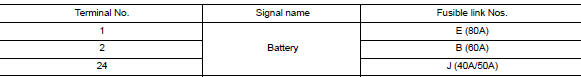
Is the fusible link blown? Yes >> replace the blown fusible link after repairing the affected circuit.
No >> go to 2
2. Check power supply circuit
- Disconnect ipdm e/r connector e42 and e44.
- Check voltage between ipdm e/r connector e42 and e44 and ground.
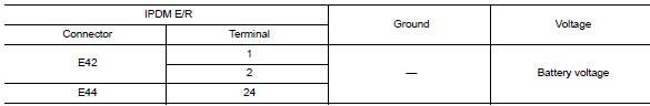
Is the inspection result normal? Yes >> go to 3
No >> repair harness or connectors.
3. Check ground circuit
- Turn ignition switch OFF.
- Disconnect ipdm e/r connector e47 and e48.
- Check continuity between ipdm e/r connector e47 and e48 and ground.
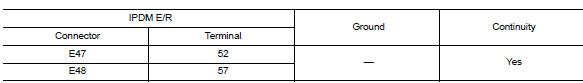
Is the inspection result normal? Yes >> inspection end.
No >> repair harness or connectors.
 Wiring diagram
Ipdm e/r (intelligent power distribution module engine room)
Wiring diagram
...
 Removal and installation
Ipdm e/r
Exploded view
Ipdm e/r
Ipdm e/r cover a
Ipdm e/r cover b
Removal and installation
Caution:
Ipdm e/r integrated relays are not serviceable and must not be removed
from unit.
...
Other materials:
P0524 Engine oil pressure
DTC Logic
DTC DETECTION LOGIC
DTC No.
CONSULT screen terms
(Trouble diagnosis content)
DTC detecting condition
Possible cause
P0524
ENGINE OIL PRESSURE
(Engine oil pressure too low)
An EOP sensor signal voltage applied to
ECM remains lower than the specified ...
Fuel pump
Component Function Check
1.CHECK FUEL PUMP FUNCTION
Turn ignition switch ON.
Pinch fuel feed hose with
two fingers.
Fuel pressure pulsation should be felt on the fuel feed
hose for 1 second after ignition switch is turned ON.
Is the inspection result normal?
YES >> INSPECT ...
B0021 Side curtain air bag module LH
Description
DTC B0021 LH SIDE CURTAIN AIR BAG MODULE
The LH side curtain air bag module is wired to the air bag diagnosis sensor
unit. The air bag diagnosis sensor
unit will monitor for opens and shorts in detected lines to the LH side curtain
air bag module.
PART LOCATION
Refer to SRC-5, ...
