Nissan Sentra Service Manual: Fuel pump
Component Function Check
1.CHECK FUEL PUMP FUNCTION
- Turn ignition switch ON.
- Pinch fuel feed hose
 with
with
two fingers.
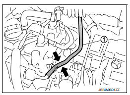
Fuel pressure pulsation should be felt on the fuel feed hose for 1 second after ignition switch is turned ON.
Is the inspection result normal? YES >> INSPECTION END
NO >> Proceed to EC-453, "Diagnosis Procedure".
Diagnosis Procedure
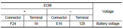
1.CHECK FUEL PUMP POWER SUPPLY CIRCUIT-1
- Turn ignition switch OFF.
- Disconnect ECM harness connector.
- Turn ignition switch ON.
- Check the voltage between ECM harness connector and ground.
Is the inspection result normal? YES >> GO TO 3.
NO >> GO TO 2.
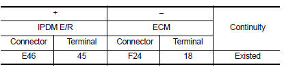
2.CHECK FUEL PUMP POWER SUPPLY CIRCUIT-2
- Turn ignition switch OFF.
- Disconnect IPDM E/R harness connector.
- Check the continuity between IPDM E/R harness connector and ECM harness connector.
- Also check harness for short to ground and short to power.
Is the inspection result normal? YES >> GO TO 8.
NO >> Repair or replace error-detected parts.
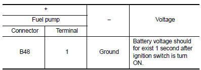
3.CHECK FUEL PUMP POWER SUPPLY CIRCUIT-3
- Turn ignition switch OFF.
- Reconnect all harness connectors disconnected.
- Disconnect fuel pump harness connector.
- Turn ignition switch ON.
- Check the voltage between fuel pump harness connector and ground.
Is the inspection result normal? YES >> GO TO 6.
NO >> GO TO 4.
4.CHECK FUSE
- Turn ignition switch OFF.
- Disconnect 15A fuse (No. 50) from IPDM E/R.
- Check 15A fuse.
Is the inspection result normal? YES >> GO TO 5.
NO >> Replace 15A fuse.
5.CHECK FUEL PUMP POWER SUPPLY CIRCUIT-4
- Turn ignition switch OFF.
- Disconnect IPDM E/R harness connector
- Check the continuity between IPDM E/R harness connector and fuel pump harness connector.
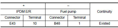
- Also check harness for short to ground and short to power.
Is the inspection result normal? YES >> GO TO 6.
NO >> Repair or replace error-detected parts.
6.CHECK FUEL PUMP GROUND CIRCUIT
- Turn ignition switch OFF.
- Check the continuity between fuel pump harness connector and ground.
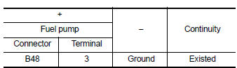
- Also check harness for short to power.
Is the inspection result normal? YES >> GO TO 7.
NO >> Repair or replace error-detected parts.
7.CHECK FUEL PUMP
Check fuel pump. Refer to EC-455, "Component Inspection (Fuel Pump)".
Is the inspection result normal? YES >> GO TO 8.
NO >> Replace fuel filter and fuel pump. Refer to FL-6, "Exploded View".
8.CHECK INTERMITTENT INCIDENT
Check intermittent incident. Refer to GI-39, "Intermittent Incident".
Is the inspection result normal? YES >> Replace IPDM E/R. Refer to PCS-30, "Removal and Installation" (With intelligent key) or PCS-58, "Removal and Installation" (Without intelligent key).
NO >> Repair or replace error-detected parts.
Component Inspection (Fuel Pump)
1.CHECK FUEL PUMP
- Turn ignition switch OFF
- Disconnect fuel level sensor unit and fuel pump harness connector.
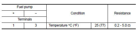
- Check resistance between fuel pump terminals as follows.
Is the inspection result normal? YES >> INSPECTION END
NO >> Replace fuel filter and fuel pump. Refer to FL-6, "Removal and Installation".
 Fuel injector
Component Function Check
1.INSPECTION START
Turn ignition switch to START.
Is any cylinder ignited?
YES >> GO TO 2.
NO >> Proceed to EC-450, "Diagnosis Procedure".
2.CH ...
 Ignition signal
Component Function Check
1.INSPECTION START
Turn ignition switch OFF.
Start engine.
Does the engine start?
YES >> GO TO 2.
NO >> Proceed to EC-456, "Diagnosis Procedure& ...
Other materials:
Cylinder block
Exploded View
Cylinder block
Block heater (for Canada)
Top ring
Second ring
Oil ring
Piston
Piston pin
Snap ring
Connecting rod
Connecting rod bearing (upper)
Connecting rod bearing (lower)
Crankshaft key
Connecting rod cap
Connecting rod cap bolt
Main bearing ca ...
Abs branch line circuit
Diagnosis procedure
1.Check connector
Turn the ignition switch off.
Disconnect the battery cable from the negative terminal.
Check the terminals and connectors of the abs actuator and electric unit
(control unit) for damage, bend
and loose connection (unit side and connector side).
...
P2118 Throttle control motor
DTC Logic
DTC DETECTION LOGIC
DTC No.
CONSULT screen terms
(Trouble diagnosis content)
DTC detecting condition
Possible cause
P2118
ETC MOT-B1
(Throttle actuator control
motor current range/
performance)
ECM detects short in both circuits between
ECM a ...
