Nissan Sentra Service Manual: Abs branch line circuit
Diagnosis procedure
1.Check connector
- Turn the ignition switch off.
- Disconnect the battery cable from the negative terminal.
- Check the terminals and connectors of the abs actuator and electric unit (control unit) for damage, bend and loose connection (unit side and connector side).
Is the inspection result normal? Yes >> go to 2.
No >> repair the terminal and connector.
2.Check harness for open circuit
- Disconnect the connector of abs actuator and electric unit (control unit).
- Check the resistance between the abs actuator and electric unit (control unit) harness connector terminals.
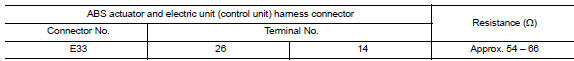
Is the measurement value within the specification? Yes >> go to 3.
No >> repair the abs actuator and electric unit (control unit) branch line.
3.Check power supply and ground circuit
Check the power supply and the ground circuit of the abs actuator and electric unit (control unit). Refer to brc-62, "diagnosis procedure".
Is the inspection result normal? Yes (present error)>>replace the abs actuator and electric unit (control unit). Refer to brc-110, "removal and installation".
Yes (past error)>>error was detected in the abs actuator and electric unit (control unit) branch line.
No >> repair the power supply and the ground circuit.
 Ecm branch line circuit
Diagnosis procedure
1.Check connector
Turn the ignition switch OFF.
Disconnect the battery cable from the negative terminal.
Check the terminals and connectors of the ECM for damage, bend and ...
 Ipdm-e branch line circuit
Diagnosis procedure
1.Check connector
Turn the ignition switch off.
Disconnect the battery cable from the negative terminal.
Check the terminals and connectors of the ipdm e/r for damage, ben ...
Other materials:
Positive crankcase ventilation
Inspection
1.CHECK PCV VALVE
With engine running at idle, remove PCV valve from rocker cover. A
properly working valve makes a hissing noise as air passes through
it. A strong vacuum should be felt immediately when a finger is
placed over valve inlet.
Is the inspection result normal?
YES &g ...
Precaution
Precaution for supplemental restraint system (srs) "air bag" and "seat
belt pre-tensioner"
The supplemental restraint system such as “air bag” and “seat belt pre-tensioner”,
used along
with a front seat belt, helps to reduce the risk or severity of injur ...
Precaution
Precaution for supplemental restraint system (srs) "air bag" and "seat
belt pre-tensioner"
The supplemental restraint system such as “air bag” and “seat belt pre-tensioner”,
used along
with a front seat belt, helps to reduce the risk or severity of injur ...
