Nissan Sentra Service Manual: Replacement operations
Description
This section is prepared for technicians who have attained a high level of skill and experience in repairing collision- damaged vehicles and also use modern service tools and equipment. Persons unfamiliar with body repair techniques should not attempt to repair collision-damaged vehicles by using this section.
Technicians are also encouraged to read Body Repair Manual (Fundamentals) in order to ensure that the original functions and quality of the vehicle can be maintained. The Body Repair Manual (Fundamentals) contains additional information, including cautions and warning, that are not including in this manual. Technicians should refer to both manuals to ensure proper repairs.
Please note that these information are prepared for worldwide usage, and as such, certain procedures might not apply in some regions or countries.
The symbols used in this section for cutting and welding/brazing operations are shown below.
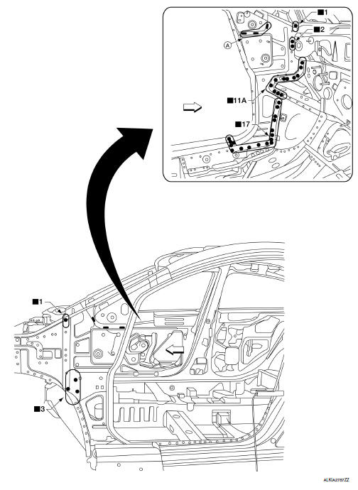
- Front pillar butt joint can be determined anywhere within shaded area as shown in the figure. The best location for the butt joint is at position A due to the construction of the vehicle. Refer to the front pillar section.
- Determine cutting position and record distance from the locating indent. Use this distance when cutting the service part. Cut outer front pillar over 60 mm above inner front pillar cut position.
- Prepare a cutting jig to make outer pillar easier to cut. Also, this will permit service part to be accurately cut at joint position.
- An example of cutting operation using a cutting jig is as follows.
- Mark cutting lines.
- Cut position of outer pillar
- Cut position of inner pillar
- Align cutting line with notch on jig. Clamp jig to pillar.
- Cut outer pillar along groove of jig. (At position A)
- Remove jig and cut remaining portions.
- Cut inner pillar at position B in same manner.
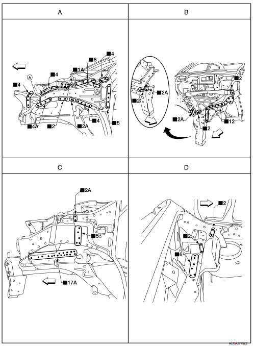
Hoodledge
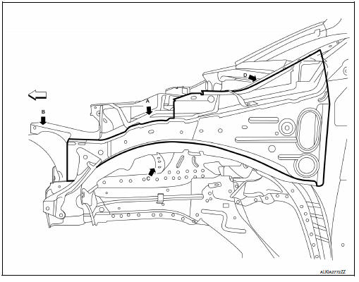
Change parts
- Front hoodledge
- Radiator core support upper
- Front strut housing (LH)
- Hoodledge connector
 Front
Front
Front Side Member
Change parts
- Front side member front assembly
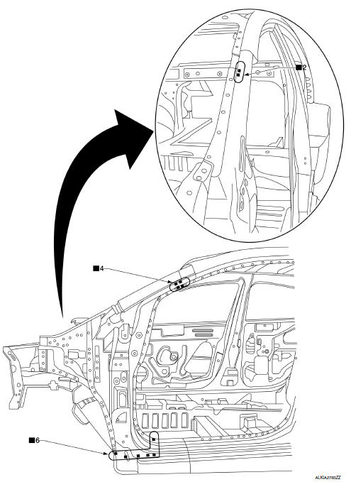
Front Pillar
OUTER
- Work after hoodledge and hoodledge reinforcement rear has been removed.
- Front pillar section of body side outer
- Recommended sectioning location
REINFORCEMENT
- Work after front pillar outer has been removed.
- Front pillar reinforcement
INNER
- Work after front pillar reinforcement has been removed.
- Front pillar inner reinforcement
- Stitch mig welds
Dash Side
Work with front pillar reinforcement removed.
- Dash side
- Stitch mig weld
Center Pillar
OUTER
Change parts
- Center pillar portion of body side outer recommended sectioning area.

- 165 mm (6.5 in)
- 140 mm (5.5 in)
- 45 mm (1.8 in)
Removal
- Use a cut off wheel to make pre-measured cut in upper center pillar outer body side.
- Cut the sill area (A) between the sill plate holes (B) on the lower center pillar outer body side.
- Drill spot welds that attach the center pillar outer body side. Only drill through the outer panel.
- Remove the center pillar outer body side.
Installation
Match welds locations from removed part onto new panel and weld into place.
REINFORCEMENT
Work after center pillar outer has been removed.
- Center pillar reinforcement
 Front
Front
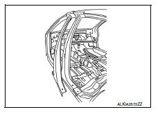
Roof
- Roof panel
 Front
Front
REMOVAL
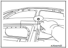
- Remove the headlining. Refer to INT-40, "Removal and Installation".
- Remove the roof side moldings (RH/LH). Refer to EXT-32, "Removal and Installation".
- Remove the windshield glass. Refer to GW-12, "Removal and Installation".
- Remove the rear window glass. Refer to GW-26, "Removal and Installation".
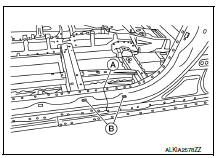
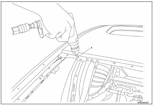
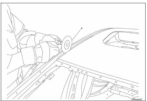
- Drill out spot welds using a 8.0 mm (0.31 in) spot weld removing bit (A) on the windshield and rear window glass flanges.
NOTE:
Only drill through the first layer of metal (the roof outer panel)
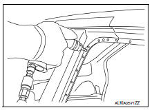
- Use an angle head grinder and a 3.18 mm (0.125 in) cutting wheel (A) to grind through the first layer only.
NOTE:
Only grind through the first layer of metal (the roof outer panel)
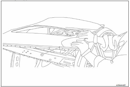
- Remove roof panel (1).
PREPARATION
- Weld through primer
 Front
Front
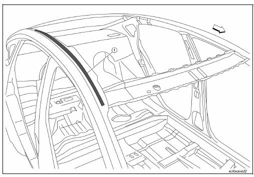
- Grind all mating surfaces around the roof flanges.
- Test panel for proper alignment and fit.
- Remove panel.
- Compare to the removed panel, then drill 8.0 mm (0.31 in) holes in the same location on the new roof panel.
- Use 3M weld through primer to prime body side upper and the front and rear window flanges
INSTALLATION
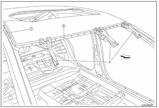
- Body side upper spot welds
- Plug welds
- Clamping pliers
 Front
Front
- Check the dimensions and fit.
- Use clamping pliers to retain the roof panel to the front and rear window flanges.
- Plug weld as necessary.
- Dress welds as necessary to allow proper glass fit.
- Refer to NISSAN approved panel refinishing
- Install the headlining. Refer to INT-40, "Removal and Installation".
- Install rear window glass. Refer to GW-26, "Removal and Installation".
- Install windshield glass. Refer to GW-12, "Removal and Installation".
- Install roof side moldings (RH/LH). Refer to EXT-32, "Removal and Installation".
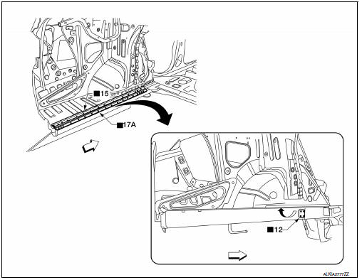
Outer Sill
Work after the front pillar reinforcement, center pillar reinforcement, and rear fender have been removed.
- Outer sill reinforcement
 Front
Front
Rear Fender
- Recommended cut zone
- Bonded hem flange
 Front
Front
Rear Panel
- Rear panel assembly
Rear Floor Rear
- Work after rear panel assembly has been removed.
- Rear floor rear
Rear Side Member Extension
- Work after rear panel assembly and rear floor rear have been removed.
- Rear side member extension
 Front
Front
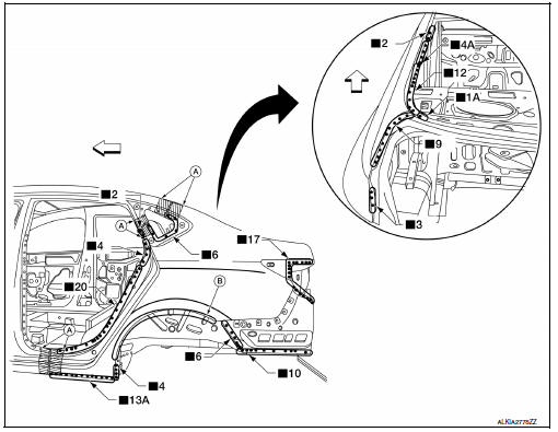
 Body sealing
Description
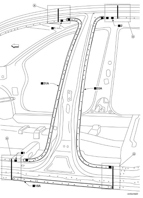
The following figure shows the areas which are sealed at the factory. Sealant
which has been applied to these
areas should be smooth and free from cuts or gaps. Care should be taken no ...

Other materials:
Basic inspection
DIAGNOSIS AND REPAIR WORKFLOW
Work Flow
OVERALL SEQUENCE
DETAILED FLOW
1.INTERVIEW CUSTOMER
Interview the customer to obtain as much information as possible about the
conditions and environment under
which the malfunction occurred.
>> GO TO 2.
2.SYMPTOM CHECK
Verify symptoms.
...
Parking brake
WARNING
Be sure the parking brake is fully released
before driving. Failure to do so
can cause brake failure and lead to an
accident.
Do not release the parking brake from
outside the vehicle.
Do not use the shift lever in place of the
parking brake. When parki ...
Shift position indicator circuit
Component Parts Function Inspection
1.CHECK SHIFT POSITION INDICATOR
Start the engine.
Shift selector lever.
Check that the selector lever position and the shift position indicator
on the combination meter are identical.
Is the inspection result normal?
YES >> INSPECTION END
N ...
