Nissan Sentra Service Manual: Rear bumper
Exploded view
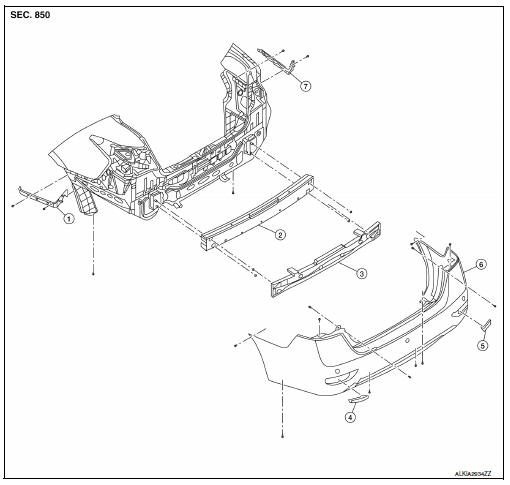
- Rear bumper side bracket (LH)
- Rear bumper reinforcement
- Rear bumper energy absorber
- Rear bumper fascia reflector (LH)
- Rear bumper fascia reflector (RH)
- Rear bumper fascia
- Rear bumper side bracket (RH)
 Pawl
Pawl
Removal and installation
CAUTION:
Bumper fascia is made of resin. Use care when handling to prevent damage. Avoid contact with oily substances.
REMOVAL
- Remove rear combination lamps (LH/RH). Refer to EXL-126, "Removal and Installation".
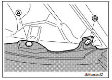
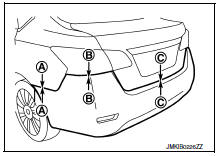
- Remove the clips (A) (LH/RH) and bolts (B) (LH/RH) from the rear bumper fascia upper side.
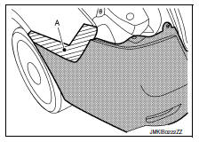
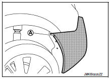
- Apply protective tape (A) to protect the components from damage on each side as shown.
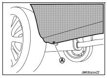
- Remove clips (A) (LH/RH) from rear bumper fascia lower side.
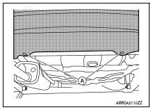
- Remove bolts (A) (LH/RH) from rear bumper fascia lower side.
- Remove rear bumper fascia screws (A) (LH/RH).
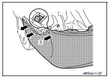
- Release the rear bumper fascia from the rear bumper fascia side bracket on each side (LH/RH) as shown.
 : Pawl
CAUTION:
When removing rear bumper fascia, two people are required as to avoid damaging.
- Remove rear bumper fascia.
- Remove the rear bumper fascia reflectors (LH/RH) from rear bumper fascia.
- Remove rear bumper energy absorber.
- Remove rear bumper side bracket screws and the rear bumper side brackets (LH/RH).
INSTALLATION
Installation is in the reverse order of removal.
NOTE:
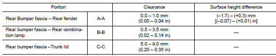
- The following table shows the specified values for checking normal installation status.
- Fitting adjustment cannot be performed.
 Front bumper
Exploded view
Grommet
Front bumper side bracket (RH)
Front under cover
Front air spoiler
Front bumper reinforcement
Front energy absorber
Front fog lamp (RH) (if equipped)
Front ...
 Front grille
Exploded view
Core support cover
Front grille
Emblem
Pawl
Removal and installation
REMOVAL
Remove core support cover bolts (A), clips (B) and core support
cover (1).
...
Other materials:
Low tire pressure warning lamp blinks
Diagnosis Procedure
NOTE:
If low tire pressure warning lamp repeats blinking ON for 2 seconds and
OFF for 0.2 seconds, wake-up operation
for all transmitters is not complete.
Carry out transmitter wake-up operation. Refer to WT-22, "Work Procedure".
1.CHECK BCM CONNECTOR
Turn ...
NISSAN vehicle immobilizer system
The NISSAN Vehicle Immobilizer system will not
allow the engine to start without the use of the
registered key.
If the engine fails to start using a registered key
(for example, when interference is caused by
another registered key, an automated toll road
device or automatic payment device o ...
P1148 Closed loop control
DTC Logic
DTC DETECTION LOGIC
NOTE:
DTC P1148 is displayed with DTC for A/F sensor 1.
When the DTC is detected, perform the trouble diagnosis of DTC corresponding to
A/F sensor 1.
DTC No.
CONSULT screen terms
(Trouble diagnosis content)
DTC detecting condition
Possible ca ...
