Nissan Sentra Service Manual: Front bumper
Exploded view
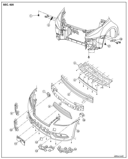
- Grommet
- Front bumper side bracket (RH)
- Front under cover
- Front air spoiler
- Front bumper reinforcement
- Front energy absorber
- Front fog lamp (RH) (if equipped)
- Front bumper lower grille
- Front bumper fascia finisher (RH) (if equipped)
- Front fog lamp finisher (RH) (if equipped)
- License plate bracket
- Tow cover
- Front fog lamp finisher (LH) (if equipped)
- Front bumper fascia finisher (LH) (if equipped)
- Front bumper fascia
- Front fog lamp (LH) (if equipped)
- Grommet
- Front bumper side bracket (LH)
 Pawl
Pawl
Removal and installation
CAUTION:
Bumper fascia is made of resin. Use care when handling to prevent damage. Avoid contact with oily substances.
REMOVAL
- Remove front grille. Refer to EXT-23, "Removal and Installation".
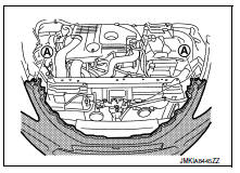
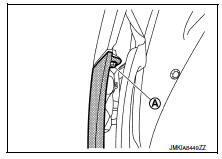
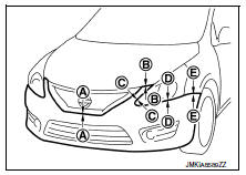
- Remove front bumper fascia clips (A) from front bumper fascia upper side.
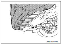
- Remove front bumper fascia clips (A) from front bumper fascia lower side.
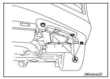
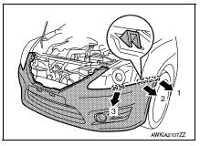
- Remove fender protector bolts (A) (LH/RH).
- Remove front bumper fascia screws (A) (LH/RH).
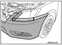
- Apply protective tape (A) to protect the component from damage on each side as shown.
- Release the front bumper fascia to release from the front bumper fascia side bracket on each side (LH/RH) as shown.
 : Pawl
CAUTION:
When removing front bumper fascia two people are required to avoid damaging.
- Disconnect the harness connectors from the front fog lamps (if equipped).
- Remove the front bumper fascia.
- Release front fog lamp finisher pawls, then remove front fog lamp finishers (LH/RH).
 Pawl
Pawl
- Remove the front fog lamp assemblies (LH/RH) (if equipped) from front bumper fascia. Refer to EXL-122, "Removal and Installation".
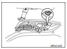
- Remove front bumper energy absorber.
- Remove front bumper reinforcement nuts and the front bumper reinforcement.
- Remove front bumper side bracket screws and the front bumper side brackets (LH/RH).
- Remove front under cover bolts, clips and front under cover.
INSTALLATION
Installation is in the reverse order of removal.
NOTE:
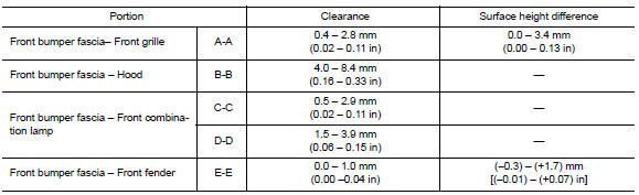
- The following table shows the specified values for checking normal installation status.
- Fitting adjustment cannot be performed.

 Rear bumper
Exploded view
Rear bumper side bracket (LH)
Rear bumper reinforcement
Rear bumper energy absorber
Rear bumper fascia reflector (LH)
Rear bumper fascia reflector (RH)
Rear bumper fasc ...
Other materials:
Trunk room lamp
Removal and Installation
Warning:
Do not touch bulb while it is lit or right after being turned off.
Burning may result.
Caution:
Do not touch glass surface of the bulb with bare hands or allow oil or
grease to get on it to prevent
damage to bulb.
Release the tab (b) to open the lens.
...
DTC/circuit diagnosis
U1000 can comm
Description
Refer to LAN-7, "CAN COMMUNICATION SYSTEM : System Description".
Dtc logic
DTC DETECTION LOGIC
NOTE:
U1000 can be set if a module harness was disconnected and reconnected,
perhaps during a repair. Confirm
that there are actual CAN diagnostic symptoms a ...
