Nissan Sentra Service Manual: 2135 TP Sensor
DTC Logic
DTC DETECTION LOGIC
NOTE:
If DTC P2135 is displayed with DTC P0643, first perform the trouble diagnosis for DTC P0643. Refer to EC-353, "DTC Logic".
| DTC No. | CONSULT screen terms (Trouble diagnosis content) | DTC detecting condition | Possible cause |
| P2135 | TP SENSOR-B1 (Throttle/Pedal position sensor/switch “A” / “B” voltage correlation) | Rationally incorrect voltage is sent to ECM compared with the signals from TP sensor 1 and TP sensor 2. |
|
DTC CONFIRMATION PROCEDURE
1.PRECONDITIONING
If DTC Confirmation Procedure has been previously conducted, always perform the following procedure before conducting the next test.
- Turn ignition switch OFF and wait at least 10 seconds.
- Turn ignition switch ON.
- Turn ignition switch OFF and wait at least 10 seconds.
TESTING CONDITION:
Before performing the following procedure, confirm that battery voltage is more than 8 V at idle.
>> GO TO 2.
2.PERFORM DTC CONFIRMATION PROCEDURE
- Start engine and let it idle for 1 second.
- Check DTC.
Is DTC detected? YES >> Proceed to EC-438, "Diagnosis Procedure".
NO >> INSPECTION END
Diagnosis Procedure
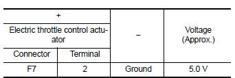
1.CHECK THROTTLE POSITION SENSOR POWER SUPPLY
- Turn ignition switch OFF.
- Disconnect electric throttle control actuator harness connector.
- Turn ignition switch ON.
- Check the voltage between electric throttle control actuator harness connector and ground.
Is the inspection result normal? YES >> GO TO 3.
NO >> GO TO 2.
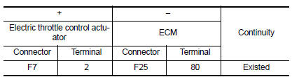
2.CHECK THROTTLE POSITION SENSOR POWER SUPPLY CIRCUIT
- Turn ignition switch OFF.
- Disconnect ECM harness connector
- Check the continuity between electric throttle control actuator harness connector and ground.
- Also check harness for short to ground.
Is the inspection result normal? YES >> Perform the trouble diagnosis for power supply circuit.
NO >> Repair or replace error-detected parts.
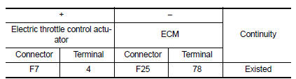
3.CHECK THROTTLE POSITION SENSOR GROUND CIRCUIT
- Turn ignition switch OFF.
- Disconnect ECM harness connector.
- Check the continuity between electric throttle control actuator harness connector and ECM harness connector.
- Also check harness for short to power.
Is the inspection result normal? YES >> GO TO 4.
NO >> Repair or replace error-detected parts.
4.CHECK THROTTLE POSITION SENSOR INPUT SIGNAL CIRCUIT
- Check the continuity between electric throttle control actuator harness connector and ECM harness connector.
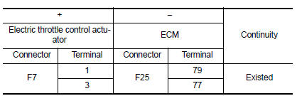
- Also check harness for short to ground and to power.
Is the inspection result normal? YES >> GO TO 5.
NO >> Repair open circuit or short to ground or short to power in harness or connectors.
5.CHECK THROTTLE POSITION SENSOR
Check throttle position sensor. Refer to EC-439, "Component Inspection (TP Sensor)".
Is the inspection result normal? YES >> Check intermittent incident. Refer to GI-39, "Intermittent Incident".
NO >> Replace electric throttle control actuator. Refer to EM-27, "Removal and Installation".
Component Inspection (TP Sensor)
1.CHECK THROTTLE POSITION SENSOR
- Turn ignition switch OFF.
- Reconnect all harness connectors disconnected.
- Perform “ Throttle Valve Closed Position Learning”. Refer to EC-139, "Work Procedure".
- Turn ignition switch ON.
- Set selector lever to D (CVT) or 1st (M/T) position.
- Check the voltage between ECM harness connector terminals as per the following conditions.
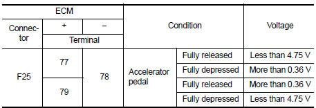
Is the inspection result normal? YES >> INSPECTION END
NO >> Replace electric throttle control actuator. Refer to EM-27, "Removal and Installation".
 P2127, P2128 APP Sensor
DTC Logic
DTC DETECTION LOGIC
DTC No.
CONSULT screen terms
(Trouble diagnosis content)
DTC detecting condition
Possible cause
P2127
APP SEN 2/CIRC
(Throttle/Pedal p ...
 P2138 APP Sensor
DTC Logic
DTC DETECTION LOGIC
NOTE:
If DTC P2138 is displayed with DTC P0643, first perform the trouble
diagnosis for DTC P0643. Refer to
EC-353, "DTC Logic".
DTC No.
CONSUL ...
Other materials:
System description
Component parts
Component parts location
Ipdm e/r (contains ignition relay-1)
Bcm (view with instrument panel removed)
Fuse block (j/b) (front)
Fuse block (j/b) (back)
Blower relay
Ignition relay-2
Accessory relay-1
Push-button ignition switch
Component description
...
B0028 Side airbag module RH
Description
DTC B0028 FRONT RH SIDE AIR BAG MODULE
The front RH side air bag module is wired to the air bag diagnosis sensor
unit. The air bag diagnosis sensor
unit will monitor for opens and shorts in detected lines to the front RH side
air bag module.
PART LOCATION
Refer to SRC-5, " ...
Precaution for Work
When removing or disassembling each component, be careful not to damage
or deform it. If a component
may be subject to interference, be sure to protect it with a shop cloth.
When removing (disengaging) components with a screwdriver or similar
tool, be sure to wrap the component
with a ...
