Nissan Sentra Service Manual: B0021 Side curtain air bag module LH
Description
DTC B0021 LH SIDE CURTAIN AIR BAG MODULE
The LH side curtain air bag module is wired to the air bag diagnosis sensor unit. The air bag diagnosis sensor unit will monitor for opens and shorts in detected lines to the LH side curtain air bag module.
PART LOCATION
Refer to SRC-5, "Component Parts Location".
DTC Logic
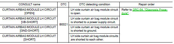
DTC DETECTION LOGIC
With CONSULT
DTC CONFIRMATION PROCEDURE (With CONSULT)
1.CHECK SELF-DIAG RESULT
- Turn ignition switch ON.
- Check for DTC using CONSULT.
Is the DTC detected? YES (Current DTC)>>Refer to SRC-54, "Diagnosis Procedure".
YES (Past DTC)>>GO TO 2.
NO >> Inspection End.
2.ERASE SELF-DIAG RESULT
Erase the DTC using CONSULT.
Can the DTC be erased? YES >> Inspection End.
NO >> Refer to SRC-54, "Diagnosis Procedure".
DTC CONFIRMATION PROCEDURE (Without CONSULT)
1.CHECK SELF-DIAG RESULT
- Turn ignition switch ON.
- Check the air bag warning lamp status. Refer to SRC-17, "Trouble Diagnosis without CONSULT".
NOTE:
SRS will not enter diagnosis mode if no malfunction is detected in user mode.
Is the DTC detected? YES >> Refer to SRC-54, "Diagnosis Procedure".
NO >> Inspection End.
Diagnosis Procedure
1.HARNESS CONNECTOR
Visually inspect all applicable harness connectors for the following:
- Visible damage to connector or terminal
- Loose terminal
- Poor connection
NOTE:
All harness connectors should be inspected from the air bag diagnosis sensor unit to the end component (including any in-line connectors).
Is the inspection result normal? YES >> GO TO 2.
NO >> Perform one of the following repairs:
- Visible damage: Replace the harness.
- Loose terminal: Secure the terminal.
- Poor connection: Secure the connection
2.CONFIRM DTC
- Reconnect all harness connectors.
- Turn ignition switch ON.
- Check for DTC using CONSULT.
Is DTC still current? YES >> GO TO 3.
NO >> Refer to GI-39, "Intermittent Incident".
3.WIRING HARNESS
Check the wiring harness for visible damage.
NOTE:
The entire wiring harness should be inspected from the air bag diagnosis sensor unit to the end component (including any in-line connectors).
Is the inspection result normal? YES >> GO TO 4.
NO >> Replace the harness.
4.CONFIRM DTC
- Reconnect all harness connectors.
- Turn ignition switch ON.
- Check for DTC using CONSULT
Is DTC still current? YES >> GO TO 5.
NO >> Refer to GI-39, "Intermittent Incident".
5.AIR BAG DIAGNOSIS SENSOR UNIT
- Replace the air bag diagnosis sensor unit. Refer to SR-28, "Removal and Installation".
- Turn ignition switch ON.
- Check for DTC using CONSULT.
Is DTC still current? YES >> GO TO 6.
NO >> Clear DTC. Inspection End.
6.SIDE CURTAIN AIR BAG MODULE LH
- Replace the side curtain air bag module LH. Refer to SR-22, "Removal and Installation".
- Turn ignition switch ON.
- Check for DTC using CONSULT.
Is DTC still current? YES >> GO TO 7.
NO >> Clear DTC. Inspection End.
7.RELATED HARNESS
Replace the related harness.
>> END
 B0020 Side airbag module LH
Description
DTC B0020 FRONT LH SIDE AIR BAG MODULE
The front LH side air bag module is wired to the air bag diagnosis sensor
unit. The air bag diagnosis sensor
unit will monitor for opens and sh ...
 B0028 Side airbag module RH
Description
DTC B0028 FRONT RH SIDE AIR BAG MODULE
The front RH side air bag module is wired to the air bag diagnosis sensor
unit. The air bag diagnosis sensor
unit will monitor for opens and sh ...
Other materials:
Voice Adaptation (VA) mode
Voice Adaptation allows up to two out-of-dialect
users to train the system to improve recognition
accuracy. By repeating a number of commands,
the users can create a voice model of their own
voice that is stored in the system. The system is
capable of storing a different voice adaptation
model ...
Rear window defogger relay
Description
Power is supplied to the rear window defogger with BCM control.
Component Function Check
1. Check rear window defogger relay power supply circuit
Turn ignition switch ON.
Check that an operation noise of rear window defogger relay (located in
IPDM E/R) can be heard when
t ...
Fuel recommendation
Use unleaded regular gasoline with an octane
rating of at least 87 AKI (Anti-Knock Index) number
(Research octane number 91).
CAUTION
Only vehicles with the E-85 filler door
label can operate on E-85. Fuel system
or other damage can occur if E-85 is
used in vehicles that are not designe ...
