Nissan Sentra B18 (2020-2025) Service Manual: Drive Belt
Exploded View
|
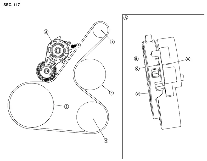
1. |
Generator |
2. |
Drive belt auto tensioner |
3. |
Crankshaft pulley |
|
4. |
A/C compressor |
5. |
Water pump |
A. |
View A |
|
B. |
Minimum belt length indicator |
C. |
Maximum belt length indicator |
D. |
Indicator mark |
Removal and Installation
REMOVAL
Remove wheel and tire (RH). Refer to Removal and Installation.
Partially remove fender protector. Refer to Exploded View.
Securely hold hexagonal part of the drive belt auto tensioner with a suitable tool and rotate it clockwise.
CAUTION:
Avoid placing hands in a location where pinching may occur if suitable tool accidentally comes off.
Insert a
suitable tool approximately 6 mm (0.24 in) in diameter into the
hole of the retaining boss to secure drive belt auto
tensioner. Note: 
Keep drive belt auto tensioner arm locked after drive belt is removed.
Remove drive belt.
INSTALLATION
Install drive belt onto all pulleys.
CAUTION:
-
Avoid placing hands in location where pinching may occur if suitable tool accidentally comes off.
-
Check that drive belt path is correct.
-
Check the drive belt is securely inside the groove on each pulley.
-
Check for engine oil, engine coolant and other oil or grease on the drive belt and surrounding locations.
Release drive belt auto tensioner and apply tension to drive belt.
Turn crankshaft pulley several times clockwise to equalize tension between each pulley.
Installation of the remaining components is in the reverse order of removal.
Inspection
|
1. |
Generator |
2. |
Drive belt auto tensioner |
3. |
Crankshaft pulley |
|
4. |
A/C compressor |
5. |
Water pump |
A. |
View A |
|
B. |
Minimum belt length indicator |
C. |
Maximum belt length indicator |
D. |
Indicator mark |
Warning:
Be sure to perform the these steps when engine is stopped.
Check that
the indicator mark (D) on fixed side of drive belt auto tensioner
is within minimum belt length indicator (B) and maximum belt length
indicator (C) range. Note:
-
Check the drive belt auto tensioners indication when the engine is cold.
-
When new drive belt is installed, the indicator mark on fixed side should be within minimum belt length indicator (B) and maximum belt length indicator (C) range.
Visually check entire drive belt for wear, damage or cracks.
If the indicator mark on the fixed side is out of the possible use range or drive belt are damaged, replace drive belt.
 Air Cleaner Filter
Exploded View
Exploded View
1.
Mass air flow sensor
...
 Spark Plug
Exploded View
Exploded View
1.
Ignition coil
2.
...
Other materials:
Trunk room lamp circuit
Description
Controls the trunk room lamp (ground side) to turn the trunk room lamp on and
off.
Diagnosis Procedure
Regarding wiring diagram information, refer to inl-17, "wiring diagram".
Caution:
Before performing the diagnosis, check that the following are normal.
Interior roo ...
Exploded View
Exploded View
1.
Compressor
Front
...
Positive crankcase ventilation
Inspection
1.CHECK PCV VALVE
With engine running at idle, remove PCV valve from rocker cover. A
properly working valve makes a hissing noise as air passes through
it. A strong vacuum should be felt immediately when a finger is
placed over valve inlet.
Is the inspection result normal?
YES &g ...
