Nissan Sentra B18 (2020-2025) Service Manual: Periodic Maintenance
Air Cleaner Filter
Exploded View
Exploded View
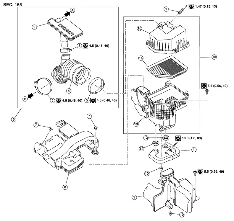
|
1. |
Mass air flow sensor |
2. |
Resonator duct |
3. |
Clamp |
|
4. |
Air duct |
5. |
Clamp |
6. |
Air duct and resonator assembly |
|
7. |
Clip |
8. |
Air inlet duct |
9. |
Resonator |
|
10. |
Mounting rubber |
11. |
Air cleaner bracket |
12. |
Grommet |
|
13. |
Air cleaner case (lower) |
14. |
Air cleaner filter |
15. |
Air cleaner assembly |
|
16. |
Air cleaner case (upper) |
A. |
To blow-by hose. Refer to Exploded View. |
B. |
To electric throttle control actuator. Refer to Exploded View. |
Removal and Installation
Removal and Installation
REMOVAL
Release clips and separate the air cleaner case (upper) from the air cleaner case (lower).
Remove the air cleaner filter.
INSTALLATION
Installation is in the reverse order of removal.
Inspection (viscous Paper Type)
Inspection (Viscous Paper Type)
INSPECTION AFTER REMOVAL
Examine with eyes that there is no stain, clogging, or damage on air cleaner filter.
-
Remove dusts (such as dead leafs) on air cleaner filter surface and inside cleaner case.
-
If clogging or damage is observed, replace the air cleaner filter.
CAUTION:
Do not clean the viscous paper type air cleaner filter by blowing as there is a risk of deterioration of its performance
MAINTENANCE INTERVAL
Refer to Introduction of Periodic Maintenance.
Drive Belt
Exploded View
Exploded View
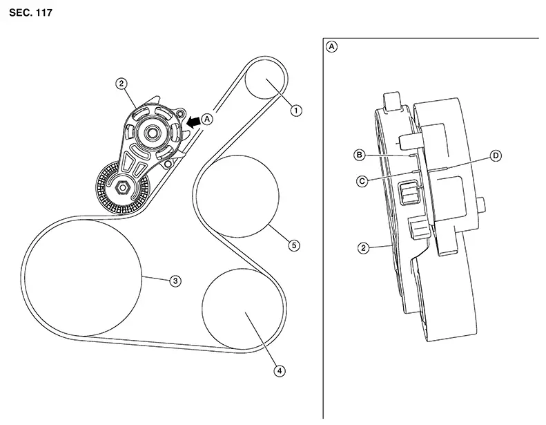
|
1. |
Generator |
2. |
Drive belt auto tensioner |
3. |
Crankshaft pulley |
|
4. |
A/C compressor |
5. |
Water pump |
A. |
View A |
|
B. |
Minimum belt length indicator |
C. |
Maximum belt length indicator |
D. |
Indicator mark |
Removal and Installation
Removal and Installation
REMOVAL
Remove wheel and tire (RH). Refer to Removal and Installation.
Partially remove fender protector. Refer to Exploded View.
Securely hold hexagonal part of the drive belt auto tensioner with a suitable tool and rotate it clockwise.
CAUTION:
Avoid placing hands in a location where pinching may occur if suitable tool accidentally comes off.
Insert a
suitable tool approximately 6 mm (0.24 in) in diameter into the
hole of the retaining boss to secure drive belt auto
tensioner. Note: 
Keep drive belt auto tensioner arm locked after drive belt is removed.
Remove drive belt.
INSTALLATION
Install drive belt onto all pulleys.
CAUTION:
-
Avoid placing hands in location where pinching may occur if suitable tool accidentally comes off.
-
Check that drive belt path is correct.
-
Check the drive belt is securely inside the groove on each pulley.
-
Check for engine oil, engine coolant and other oil or grease on the drive belt and surrounding locations.
Release drive belt auto tensioner and apply tension to drive belt.
Turn crankshaft pulley several times clockwise to equalize tension between each pulley.
Installation of the remaining components is in the reverse order of removal.
Inspection
Inspection
|
1. |
Generator |
2. |
Drive belt auto tensioner |
3. |
Crankshaft pulley |
|
4. |
A/C compressor |
5. |
Water pump |
A. |
View A |
|
B. |
Minimum belt length indicator |
C. |
Maximum belt length indicator |
D. |
Indicator mark |
Warning:
Be sure to perform the these steps when engine is stopped.
Check that
the indicator mark (D) on fixed side of drive belt auto tensioner
is within minimum belt length indicator (B) and maximum belt length
indicator (C) range. Note:
-
Check the drive belt auto tensioners indication when the engine is cold.
-
When new drive belt is installed, the indicator mark on fixed side should be within minimum belt length indicator (B) and maximum belt length indicator (C) range.
Visually check entire drive belt for wear, damage or cracks.
If the indicator mark on the fixed side is out of the possible use range or drive belt are damaged, replace drive belt.
Spark Plug
Exploded View
Exploded View
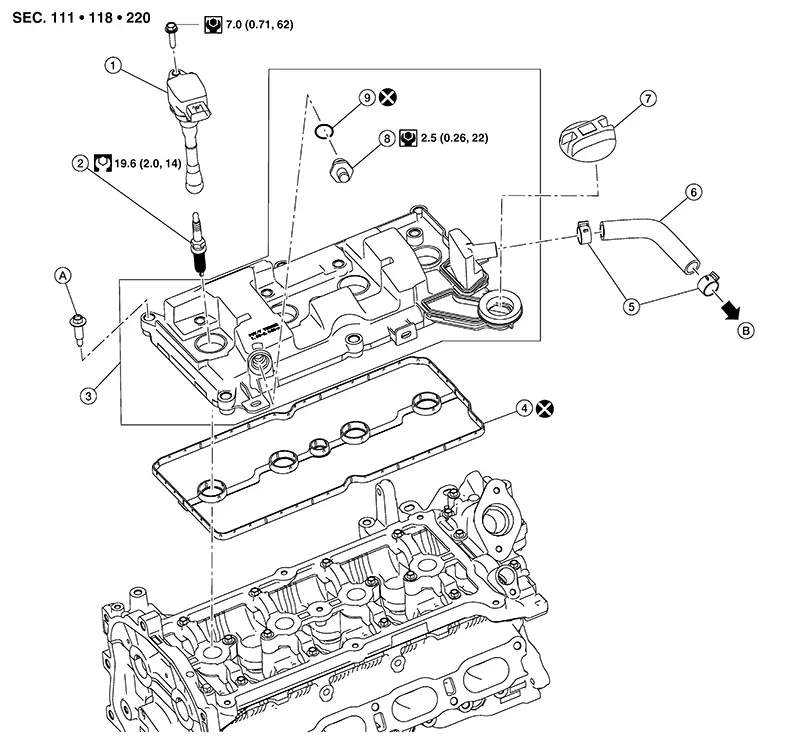
|
1. |
Ignition coil |
2. |
Spark plug |
3. |
Rocker cover assembly |
|
4. |
Rocker cover gasket |
5. |
Clamp |
6. |
Blow-by hose |
|
7. |
Oil filler cap |
8. |
PCV valve |
9. |
O-ring |
|
A. |
Refer to Removal and Installation. |
B. |
To resonator duct. Refer to Exploded View. |
Removal and Installation
Removal and Installation
REMOVAL
Remove ignition coil. Refer to Removal and Installation.
Remove
spark plug with Tool.
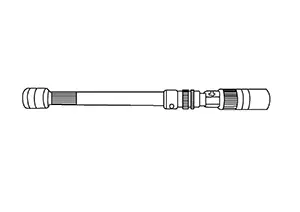
CAUTION:
Do not drop or shock spark plug.
|
Tool number |
: — (NI-48891) |
After removal, inspect the spark plug. Refer to Inspection.
INSTALLATION
Installation is in the reverse order of removal.
|
Make |
DENSO |
|
Standard type* |
DXE22H11C |
|
Gap (nominal) |
1.1 mm (0.043in) |
*: Always check with the Parts Department for the latest parts information.
Inspection
Inspection
INSPECTION AFTER REMOVAL
Use the standard type spark plug for normal condition.
|
Spark plug (Standard type) |
: Refer to Spark Plug. |
CAUTION:
-
Do not drop or shock spark plug.
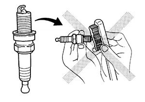
-
Do not use a wire brush for cleaning.
-
If spark plug tip is covered with carbon, spark plug cleaner may be used.
|
Cleaner air pressure |
: Less than 588 kPa (6 kg/cm2, 85 psi) |
|
Cleaning time |
: Less than 20 seconds |
-
Checking and adjusting spark plug gap is not required between replacement intervals.
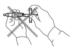
-
Measure spark plug gap. when it exceeds the limit, replace spark plug even if it is with in the specified replacement mileage. Refer to Spark Plug.
Other materials:
Egr Cooler
Exploded View
Exploded View
1.
Vacuum delay valve
bracket
2.
EGR cooler
bracket
...
Low Tire Pressure Warning Lamp Does Not Turn Off
Symptom Description
Symptom Description
The low tire pressure warning lamp does not turn
OFF after several seconds is passed after the engine starts.
Diagnosis Procedure
Diagnosis Procedure
CHECK TIRE PRESSURE
Ignition switch ...
Engine Mounting Insulator (rh)
Exploded View
Exploded View
CVT Models
1.
Engine mounting
insulator (LH)
2.
Engine mounting
insula ...