Nissan Sentra Service Manual: Trunk room lamp circuit
Description
Controls the trunk room lamp (ground side) to turn the trunk room lamp on and off.
Diagnosis Procedure
Regarding wiring diagram information, refer to inl-17, "wiring diagram".
Caution:
Before performing the diagnosis, check that the following are normal.
- Interior room lamp power supply
- Trunk room lamp bulb
1.Check trunk room lamp output
- Turn ignition switch OFF.
- Remove the trunk room lamp bulb.
- Check continuity between bcm harness connector and ground.
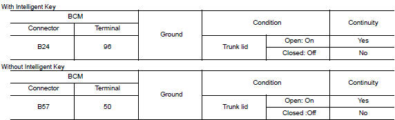
Is the inspection result normal? Yes >> trunk room lamp control circuit is operating normally.
Fixed on>>go to 3.
Fixed off>>go to 2.
2.Check trunk room lamp open circuit
Check continuity between bcm harness connector and trunk room lamp harness connector.
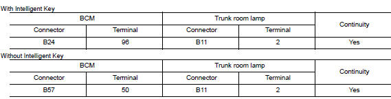
Is the inspection result normal? Yes >> check trunk room lamp for an open. If ng, replace lamp. Refer to inl-56, "removal and installation".
If ok, replace bcm. Refer to bcs-73, "removal and installation" (with intelligent key), bcs-126, "removal and installation" (without intelligent key).
No >> repair or replace harness or connector.
3.Check trunk room lamp short to ground
- Disconnect bcm harness connector.
- Check continuity between BCM harness connector and ground.
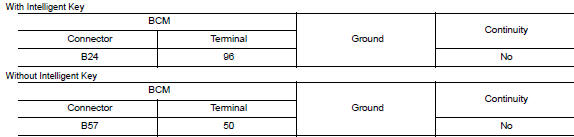
Is the inspection result normal? Yes >> check trunk room lamp for an internal short to ground. If ng, replace lamp. Refer to inl-56, "removal and installation". If ok, replace bcm. Refer to bcs-73, "removal and installation" (with intelligent key), bcs-126, "removal and installation" (without intelligent key).
No >> repair or replace harness or connector.
 Interior room lamp control circuit
Description
Controls each interior room lamp (ground side) by pwm signal.
Note:
Pwm signal control period is approximately 250 hz (in the gradual
brightening/dimming).
Component function check
...
 Push-button ignition switch illumination circuit
Description
Provides the power supply and the ground to control the push-button ignition
switch illumination.
Component function check
1.Check push-button ignition switch illumination operation ...
Other materials:
Inspection and adjustment
Additional service when replacing control unit
Additional service when replacing control unit : description
Memory reset procedure
Please observe the following instructions at confirming the moonroof
operation.
Note:
Do not disconnect the electronic power while the moonroof is operating ...
Component parts
Component parts location
Combination meter
Combination switch (lighting and turn
signal switch)
Key switch (without intelligent key system)
Push-button ignition switch (with intelligent
key system)
Seat belt buckle switch lh
Front door switch lh
Bcm
(view with instrument pane ...
Parking brake system
Inspection and Adjustment
INSPECTION
Lever Stroke
Operate the parking brake lever with a force of 196 N (20.0
kg-f, 44.1 lb-f). Check that the lever stroke is
within the specified number of notches. (Check it by listening to the clicks
of the ratchet.)
Number of notches : Refer t ...
