Nissan Sentra Service Manual: Push-button ignition switch illumination circuit
Description
Provides the power supply and the ground to control the push-button ignition switch illumination.
Component function check
1.Check push-button ignition switch illumination operation
 Consult active test
- Turn the ignition switch ON.
- Select engine sw illumi of bcm (intelligent key) active test item.
- With operating the test items, check that the push-button ignition switch illumination turns ON/OFF.
On : push-button ignition switch illumination on
Off : push-button ignition switch illumination off
Does the push-button ignition switch illumination turn on/off? Yes >> push-button ignition switch illumination circuit is normal.
No >> refer to inl-49, "diagnosis procedure".
Diagnosis procedure
Regarding wiring diagram information, refer to inl-26, "wiring diagram".
1.Check push-button ignition switch illumination power supply output
- Turn the ignition switch OFF
- Disconnect push-button ignition switch connector.
- Check voltage between push-button ignition switch harness connector and ground.
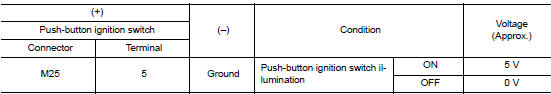
Is the inspection result normal? Yes >> go to 4.
No >> go to 2.
2.Check push-button ignition switch illumination power supply open circuit
- Disconnect bcm connector.
- Check continuity between bcm harness connector and the push-button ignition switch harness connector.
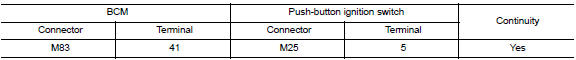
Is the inspection result normal? Yes >> go to 3.
No >> repair or replace harness or connector.
3.Check push-button ignition switch illumination power supply short circuit
Check continuity between bcm harness connector and ground.
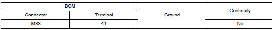
Is the inspection result normal? YES >> Replace BCM. Refer to BCS-73, "Removal and Installation" (with Intelligent Key), BCS-126, "Removal and Installation" (without Intelligent Key).
NO >> Repair or replace harness or connector.
4.Check push-button ignition switch illumination ground circuit
Check continuity between push-button ignition switch harness connector and ground.
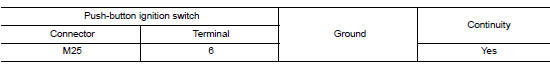
Is the inspection result normal? Yes >> replace push-button ignition switch. Refer to sec-136, "removal and installation".
No >> repair or replace harness or connector.
 Trunk room lamp circuit
Description
Controls the trunk room lamp (ground side) to turn the trunk room lamp on and
off.
Diagnosis Procedure
Regarding wiring diagram information, refer to inl-17, "wiring diagram" ...
 Symptom diagnosis
Interior lighting system symptoms
Symptom Table
Caution:
Perform the self-diagnosis with consult before the symptom diagnosis.
Perform the trouble diagnosis
if any dtc is detected.
...
Other materials:
Component parts
Component parts location
BCM (view with instrument panel removed)
Key switch
(without Intelligent Key)
Push-button ignition switch
(with Intelligent Key)
IPDM E/R
Illumination control switch
Combination switch (lighting and
turn signal switch)
Front door lock LH (key cylin ...
Indicator lights
Continuously
Variable
Transmission (CVT) position
indicator light (if so equipped)
When the ignition switch is placed in the ON
position, this indicator light shows the transmission
shift lever position. See “Driving the vehicle”
in the “Starting and driving” section of this
manual ...
P0715 Input speed sensor A
DTC Logic
DTC DETECTION LOGIC
DTC
CONSULT screen terms
(Trouble diagnosis content)
DTC detection condition
Possible causes
P0715
INPUT SPEED SENSOR A
(Input/Turbine Speed Sensor
A Circuit)
The primary speed sensor value is less than
150 r ...
