Nissan Sentra Service Manual: Diagnosis and repair workflow
Work Flow
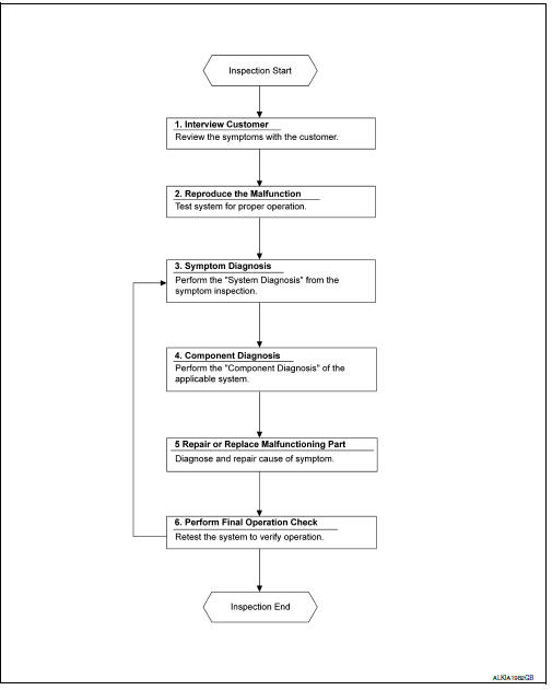
OVERALL SEQUENCE
DETAILED FLOW
1. OBTAIN INFORMATION ABOUT SYMPTOM
Interview the customer to obtain as much information as possible about the conditions and environment under which the malfunction occurred.
>> GO TO 2.
2. CONFIRM THE SYMPTOM
Check the malfunction on the vehicle that the customer describes.
Inspect the relation of the symptoms and the condition when the symptoms occur.
>> GO TO 3.
3. IDENTIFY THE MALFUNCTIONING SYSTEM WITH SYMPTOM DIAGNOSIS
Use Symptom diagnosis from the symptom inspection result in step 2 and then identify where to start performing the diagnosis based on possible causes and symptoms.
>> GO TO 4.
4. PERFORM THE COMPONENT DIAGNOSIS OF THE OF THE APPLICABLE SYSTEM
Perform the diagnosis with Component diagnosis of the applicable system.
>> GO TO 5.
5. REPAIR OR REPLACE THE MALFUNCTIONING PARTS
Repair or replace the specified malfunctioning parts.
>> GO TO 6.
6. FINAL CHECK
Check that malfunctions are not reproduced when obtaining the malfunction information from the customer, referring to the symptom inspection result in step 2.
Are the malfunctions corrected? YES >> Inspection End.
NO >> GO TO 3.
 Basic inspection
...
 Additional service when removing battery negative terminal
Description
When the battery negative terminal is disconnected, the initialization is
necessary for normal operation of
power window system.
CAUTION:
The following specified operations can not b ...
Other materials:
P1805 Brake switch
DTC Logic
DTC DETECTION LOGIC
DTC No.
CONSULT screen terms
(Trouble diagnosis content)
DTC detecting condition
Possible cause
P1805
BRAKE SW/CIRCUIT
(Brake switch circuit)
Stop lamp signal is not sent to ECM for extremely
long time while the vehicle is drivi ...
Dtc/circuit diagnosis
Power supply and ground circuit
Audio unit
AUDIO UNIT : Diagnosis Procedure
Regarding wiring diagram information, refer to av-88, "wiring diagram".
1.Check fuse
Check that the following fuses are not blown.
Are the fuses blown?
Yes >> replace the blown fuse after repairing ...
ID registration cannot be completed
Diagnosis Procedure
NOTE:
The Signal Tech II Tool (J-50190) can be used to perform the following
functions. Refer to the Signal Tech II
User Guide for additional information.
Activate and display TPMS transmitter IDs
Display tire pressure reported by the TPMS transmitter
Read TPMS DTCs
...
