Nissan Sentra Service Manual: Description
| Number | Item | Description |
| 1 | Power supply |
|
| 2 | Fusible link |
|
| 3 | Number of fusible link/ fuse |
|
| 4 | Fuse |
|
| 5 | Current rating of fusible link/fuse |
|
| 6 | Optional splice |
|
| 7 | Connector number |
|
| 8 | Splice |
|
| 9 | Page crossing |
|
| 10 | Option abbreviation |
|
| 11 | Relay |
|
| 12 | Option description |
|
| 13 | Switch |
|
| 14 | Circuit (Wiring) |
|
| 15 | System branch |
|
| 16 | Shielded line |
|
| 17 | Component name |
|
| 18 | Ground (GND) |
|
| 19 | Connector |
|
| 20 | Connectors |
|
| 21 | Wire color |
|
| B = Black W = White R = Red G = Green L = Blue Y = Yellow LG = Light Green BG = Beige BR = Brown LA = Lavender OR or O = Orange P = Pink PU or V (Violet) = Purple GY or GR = Gray SB = Sky Blue CH = Dark Brown DG = Dark Green |
||
|
||
| 22 | Terminal number |
|

 ”.
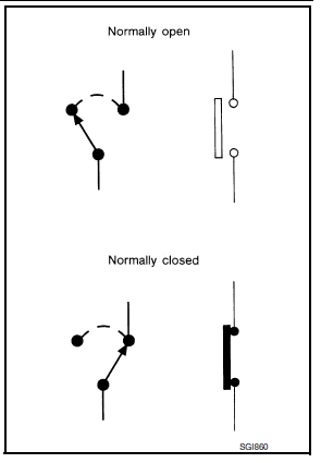
”.Switch positions
Switches are shown in wiring diagrams as if the vehicle is in the “normal” condition.
A vehicle is in the “normal” condition when:
- ignition switch is “OFF”,
- doors, hood and trunk lid/back door are closed,
- pedals are not depressed, and
- parking brake is released.
Multiple switch
The continuity of multiple switch is described in two ways as shown below.
- The switch chart is used in schematic diagrams.
- The switch diagram is used in wiring diagrams.
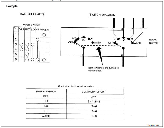
 Sample/wiring diagram -example-
For detail, refer to following GI-11, "Description".
...
 Abbreviations
Abbreviation List
The following ABBREVIATIONS are used:
A
ABBREVIATION
DESCRIPTION
A/C
Air conditioner
A/C
Air conditioning
A/F sensor
Air fuel ...
Other materials:
Moonroof unit assembly
Inspection
WIND DEFLECTOR
Open glass lid fully
Visually check for proper installation, damaged/deteriorated components,
or foreign objects within mechanism.
Correct as required for smooth operation.
Check for grease at the wind deflector arm (1) and pivot areas. If
necessary, apply ...
Preparation
Special Service Tools
NOTE:
The actual shapes of Kent-Moore tools may differ from those of special
service tools illustrated here.
Commercial Service Tools
...
Bcm branch line circuit
Diagnosis procedure
1.Check connector
Turn the ignition switch off.
Disconnect the battery cable from the negative terminal.
Check the terminals and connectors of the BCM for damage, bend and loose
connection (unit side and
connector side).
Is the inspection result normal?
YES > ...
