Nissan Sentra Service Manual: System description
Component parts
Component parts location
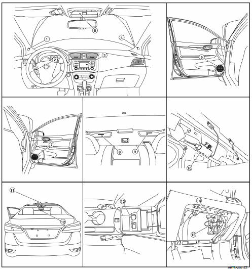
- Front tweeter LH
- Steering switches
- Audio unit
- Front tweeter rh
- Microphone
- Front door speaker lh
- Front door speaker rh
- Rear speaker rh
- Rear speaker lh
- Antenna amp.
- Satellite antenna
- Window antenna
- Usb interface
- BluetoothВ® control unit
- BluetoothВ® antenna
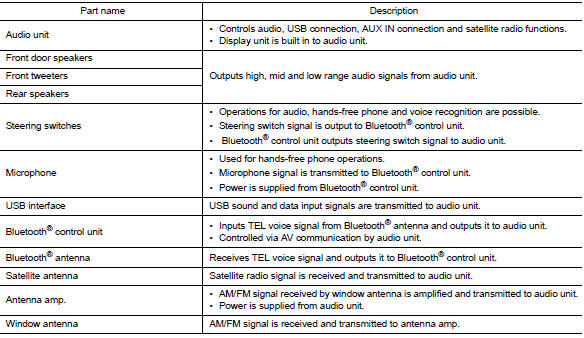
Component description
System
System diagram
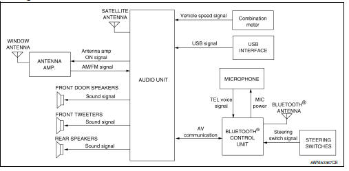
System description
Audio system
The audio system consists of the following components
- Audio unit
- Front door speakers
- Front tweeters
- Rear speakers
- Steering switches
- Usb interface
- Satellite antenna
- Antenna amp.
- Window antenna
When the audio system is on, am/fm signals received by the window antenna are amplified by the antenna amp. And sent to the audio unit. The audio unit then sends audio signals to the front door speakers, front tweeters and rear speakers.
Refer to owner's manual for audio system operating instructions.
Hands-free phone system
System operation
Note:
Cellular telephones must have their wireless connection set up (paired) before using the bluetoothВ® telephone system.
The bluetoothВ® telephone system allows users who have a bluetoothВ® cellular telephone to make a wireless connection between their cellular telephone and the bluetoothВ® control unit. Hands-free cellular telephone calls can be sent and received. Some bluetoothВ® cellular telephones may not be recognized by the bluetoothВ® control unit. When a cellular telephone or the bluetoothВ® control unit is replaced, the telephone must be paired with the bluetoothВ® control unit. Different cellular telephones may have different pairing procedures, refer to the cellular telephone operating manual.
Refer to the owner's manual for bluetoothВ® telephone system operating instructions.
BluetoothВ® control unit
When the ignition switch is turned to acc or on, the bluetoothВ® control unit will power up. During power up, the bluetoothВ® control unit is initialized and performs various self-checks. Initialization may take up to 20 seconds.
If a phone is present in the vehicle and paired with the bluetoothВ® control unit, nissan voice recognition Will then become active. BluetoothВ® telephone functions can be turned off using the nissan voice recognition system.
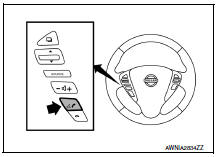
Steering switches
When buttons on the steering switches are pushed, the resistance in steering wheel audio control switch circuit changes, depending on which button is pushed. The bluetoothВ® control unit uses this signal to perform various functions while navigating through the voice recognition system.
The following functions can be performed using the steering switches:
- Initiate self-diagnosis of the bluetoothВ® telephone system
- Start a voice recognition session
- Answer and end telephone calls
- Adjust the volume of calls
Microphone
The microphone is located in the roof console assembly. The microphone sends a signal to the bluetoothВ® control unit. The microphone can be actively tested during self-diagnosis.
Audio unit
The audio unit receives signals from the bluetoothВ® control unit and sends audio signals to the speakers.
Speed sensitive volume system
Volume level of this system goes up and down automatically in proportion to the vehicle speed. The control level can be selected by the customer. Refer to Owner's Manual for operating instructions.
Diagnosis system (audio unit)
Description
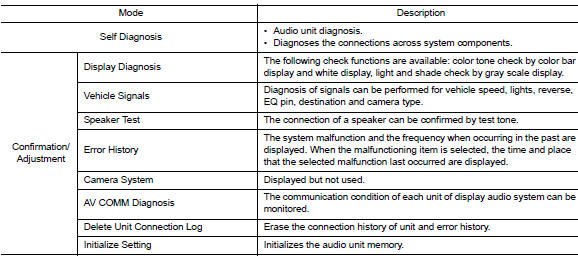
The audio unit on board diagnosis performs the functions listed in the table below:
On board diagnosis function
Method of starting
- Turn the ignition on.
- Turn the audio system OFF.
- While pressing the preset 1 button, turn the volume control dial clockwise or counterclockwise for 40 clicks or more. Shifting from current screen to previous screen is performed by pressing back button
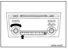
- The trouble diagnosis initial screen is displayed, and self diagnosis or confirmation/adjustment can be selected.
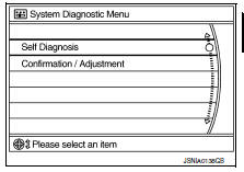
Self diagnosis mode
Audio unit self diagnosis
- Select self diagnosis.
- Self diagnosis screen is displayed. The bar graph visible in center of screen indicates progress of self diagnosis.
- Diagnosis results are displayed after the self diagnosis is completed.
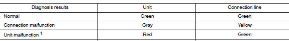
The unit names and the connection lines are color coded according to the diagnostic results.
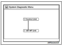
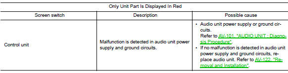
1: Control unit (audio unit) is displayed in red.
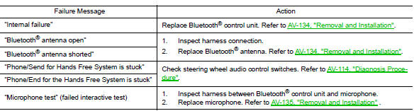
- Replace audio unit if self diagnosis did not run because control unit malfunction is indicated. The symptom is audio unit internal error. Refer to av-122, "removal and installation".
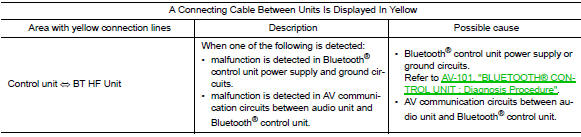
- If multiple errors occur at the same time for a single unit, the screen switch colors are determined according to the following order of priority: red > gray.
- Comments of self diagnosis results can be viewed in the diagnosis result screen.
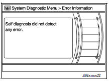
Audio unit self diagnosis results
Audio unit confirmation/adjustment
- Select confirmation/adjustment.
- Select each switch on the confirmation/adjustment screen to display the relevant trouble diagnosis screen. Press the back switch to return to the initial confirmation/adjustment screen.
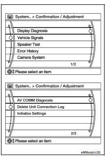
Display diagnosis
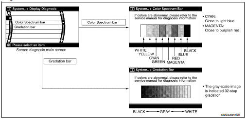
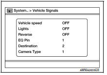
Vehicle signals
A comparison check can be made of each actual vehicle signal and the signals recognized by the system.
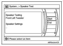
Speaker test
Select Speaker Test to display the Speaker Diagnosis screen. Press Start to generate a test tone in a speaker. Press Start again to generate a test tone in the next speaker. Press End to stop the test tones.
Error history
The self diagnosis results are judged depending on whether any error occurs from when Self Diagnosis is selected until the self diagnosis results are displayed.
However, the diagnosis results are judged normal if an error has occurred before the ignition switch is turned ON and then no error has occurred until the self diagnosis start. Check the Error Record to detect any error that may have occurred before the self diagnosis start because of this situation.
The frequency of occurrence is displayed in a count up manner. The actual count up method differs depending on the error item.
Count up method a
- The counter is set to 40 if an error occurs. 1 Is subtracted from the counter if the condition is normal at a next ignition on cycle.
- The counter lower limit is 1. The counter can be reset (no error record display) with the delete log switch.
Count up method b
- The counter increases by 1 if an error occurs when ignition switch is ON. The counter will not decrease even if the condition is normal at the next ignition ON cycle.
- The counter upper limit is 50. Any counts exceeding 50 are ignored. The counter can be reset (no error record display) with the Delete log switch.
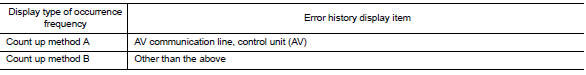
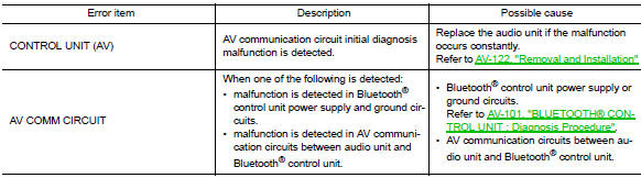
Error item
Some error items may be displayed simultaneously according to the cause. If some error items are displayed simultaneously, the detection of the cause can be performed by the combination of display items
Av comm diagnosis
- Displays the communication status between audio unit (master unit) and bluetoothВ® control unit.
- The error counter displays OK if any malfunction was not detected
in the past and displays 0 if a malfunction is detected. It increases
by 1 if the condition is normal at the next ignition switch ON cycle.
The upper limit of the counter is 39.
- The error counter is erased if reset is pressed.
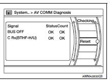
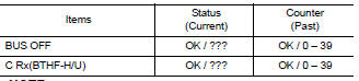
Note:
“???” Indicates unkwn.
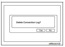
Delete unit connection log
Deletes any unit connection records and error records from the audio unit memory (clears the records of the unit that has been removed).
Initialize settings
Deletes data stored from the audio unit.
Diagnosis system (bluetoothВ® control unit)
Diagnosis Description
The bluetoothВ® control unit has two diagnostic checks. The first diagnostic check is performed automatically every ignition cycle during control unit initialization. The second diagnostic check is performed by the technician using the steering wheel audio control switches prior to trouble diagnosis.
BluetoothВ® control unit initialization checks
- Internal control unit failure
- BluetoothВ® antenna connection open or shorted
- Steering wheel audio control switches [
![(phone/end)] stuck closed](images/books/349/85/index566.gif) (phone/send),
(phone/send),
 (phone/end)] stuck closed
 - Vehicle speed pulse count
- Microphone connection test (with playback to operator)
- BluetoothВ® inquiry check
Operation procedure
- Turn ignition switch to acc or on.
- Wait for the bluetoothВ® system to complete initialization. This may take up to 20 seconds.
- Press and hold the steering wheel audio control switch
(PHONE/SEND) button for at least 5 seconds. The BluetoothВ® system will begin to play a verbal prompt.
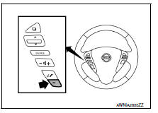
- While the prompt is playing, press and hold the steering wheel
audio control switch
 (phone/end)
button until you hear the “diagnostics mode” prompt. The bluetooth® system will sound a 5-second beep. - While the beep is sounding, press and hold the steering wheel
audio control switch
 (PHONE/END)
button again until you hear prompts. - The bluetoothВ® system has now entered into the diagnostic mode. Results of the diagnostic checks will be verbalized to the technician. Refer to av-82, "work flow".
- After the failure records are reported, an interactive microphone test will be performed. Follow the voice prompt. If the microphone test fails, refer to av-82, "work flow".
Work Flow
 Preparation
Special Service Tools
The actual shape of the tools may differ from those illustrated here.
Commercial Service Tools
...
 Ecu diagnosis information
Audio unit
Reference value
Terminal layout
Physical values
BluetoothВ® control unit
Reference Value
Terminal layout
Physical values
...
Other materials:
EPS warning lamp does not turn OFF
Description
EPS warning lamp does not turn OFF several seconds after engine
started.
Diagnosis Procedure
1.PERFORM SELF-DIAGNOSIS
With CONSULT
Turn the ignition switch OFF to ON.
Perform “EPS” self-diagnosis.
Is any DTC detected?
YES >> Check the DTC. Refer to ...
Low tire pressure warning lamp blinks
Diagnosis Procedure
NOTE:
If low tire pressure warning lamp repeats blinking ON for 2 seconds and
OFF for 0.2 seconds, wake-up operation
for all transmitters is not complete.
Carry out transmitter wake-up operation. Refer to WT-22, "Work Procedure".
1.CHECK BCM CONNECTOR
Turn ...
Door mirror
Exploded view
Door mirror cover
(with side turn signal lamp)
Door mirror housing
Door mirror actuator
Glass mirror
Door mirror cover
(without side turn signal lamp)
: Pawl
Door mirror assembly
Door mirror assembly : removal and installation
Removal
Caution:
Be careful no ...
