Nissan Sentra Service Manual: System description
Component parts
CVT CONTROL SYSTEM
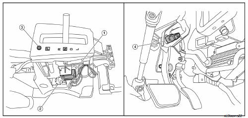
CVT CONTROL SYSTEM : Component Parts Location
| No. | Component | Function | |
| 1 | ECM | Mainly transmits the following signal to TCM via CAN
communication.
NOTE: General term for the communication (torque-down permission, torquedown request, etc.) exchanged between the ECM and TCM.
Mainly receives the following signals from TCM via CAN communication.
Refer to EC-15, "ENGINE CONTROL SYSTEM : Component Parts Location" for detailed installation location. |
|
| 2 | TCM | TM-75, "CVT CONTROL SYSTEM : TCM" | |
| 3 | BCM | Mainly transmits the following signal to TCM via CAN communication.
Refer to BCS-6, "BODY CONTROL SYSTEM : Component Parts Location" (With intelligent key system) or BCS-77, "BODY CONTROL SYSTEM : Component Parts Location" (Without intelligent key system) for detailed installation location. |
|
| 4 | ABS actuator and electric unit (control unit) | Mainly transmits the following signal to TCM via CAN communication.
Refer to BRC-7, "Component Parts Location" for detailed installation location. |
|
| 5 | Combination meter | Mainly transmits the following signal to TCM via CAN communication.
Mainly receives the following signals from TCM via CAN communication.
Refer to MWI-5, "METER SYSTEM : Component Parts Location" for detailed installation location. |
|
| 6 | ECO mode switch | DMS-24, "ECO Mode Switch" | |
| 7 | SPORT mode switch | DMS-61, "SPORT Mode Switch" | |
| 8 | Overdrive control switch | TM-82, "CVT CONTROL SYSTEM : Overdrive Control Switch" | |
| 9 | G sensor | TM-81, "CVT CONTROL SYSTEM : G Sensor" | |
| 10 | Transmission range switch | TM-75, "CVT CONTROL SYSTEM : Transmission Range Switch" | |
| 11 | Primary speed sensor | TM-76, "CVT CONTROL SYSTEM : Primary Speed Sensor" | |
| 12 | CVT unit connector | — | |
| 13 | Output speed sensor | TM-77, "CVT CONTROL SYSTEM : Output Speed Sensor" | |
| 14 | Secondary speed sensor | TM-76, "CVT CONTROL SYSTEM : Secondary Speed Sensor" | |
| 15 | Control valve | ROM assembly* | TM-75, "CVT CONTROL SYSTEM : ROM Assembly" |
| CVT fluid temperature sensor* | TM-78, "CVT CONTROL SYSTEM : CVT Fluid Temperature Sensor" | ||
| Secondary pressure sensor* | TM-78, "CVT CONTROL SYSTEM : Secondary Pressure Sensor" | ||
| Primary pressure solenoid valve* | TM-79, "CVT CONTROL SYSTEM : Primary Pressure Solenoid Valve" | ||
| Low brake solenoid valve* | TM-79, "CVT CONTROL SYSTEM : Low Brake Solenoid Valve" | ||
| High clutch & reverse brake solenoid valve* | TM-80, "CVT CONTROL SYSTEM : High Clutch & Reverse Brake Solenoid Valve" | ||
| Torque converter clutch solenoid valve* | TM-80, "CVT CONTROL SYSTEM : Torque Converter Clutch Solenoid Valve" | ||
| Line pressure solenoid valve* | TM-81, "CVT CONTROL SYSTEM : Line Pressure Solenoid Valve" | ||
*: These components are included in control valve assembly.
CVT CONTROL SYSTEM : TCM
- The TCM consists of a microcomputer and connectors for signal input and output and for power supply.
- The vehicle driving status is judged based on the signals from the sensors, switches, and other control units, and the optimal transaxle control is performed.
- For TCM control items, refer to TM-93, "CVT CONTROL SYSTEM : System Description".
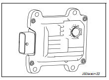
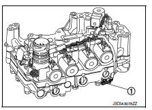
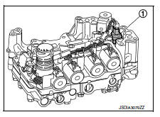
CVT CONTROL SYSTEM : ROM Assembly
- The ROM assembly
 is installed to control valve.
 - The ROM assembly stores the calibration data (characteristic value) of each solenoid valve. TCM enables accurate hydraulic control by obtaining the calibration data.
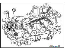
CVT CONTROL SYSTEM : Transmission Range Switch
- The transmission range switch is installed to upper part of transaxle case.
- The transmission range switch detects the selector lever position.
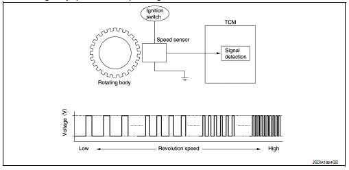
CVT CONTROL SYSTEM : Primary Speed Sensor
- The primary speed sensor is installed to side cover of transaxle.
- The primary speed sensor detects primary pulley speed.
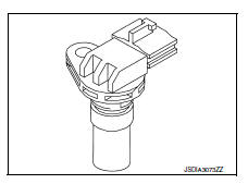
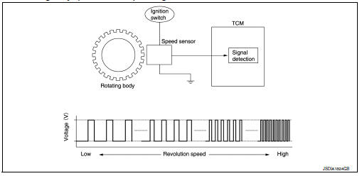
- The primary speed sensor generates an ON-OFF pulse signal according to the rotating body speed. TCM judges the rotating body speed from the pulse signal.
CVT CONTROL SYSTEM : Secondary Speed Sensor
- The secondary speed sensor is installed to side cover of transaxle.
- The secondary speed sensor detects secondary pulley speed.
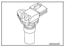
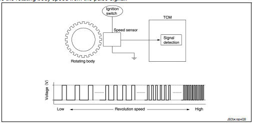
- The secondary speed sensor generates an ON-OFF pulse signal according to the rotating body speed. TCM judges the rotating body speed from the pulse signal.
CVT CONTROL SYSTEM : Output Speed Sensor
- The output speed sensor is installed to the back side of transaxle case.
- The output speed sensor detects final gear speed. TCM evaluates the vehicle speed from the final gear revolution.
- The output speed sensor generates an ON-OFF pulse signal according to the rotating body speed. TCM judges the rotating body speed from the pulse signal.
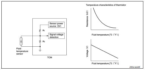
CVT CONTROL SYSTEM : CVT Fluid Temperature Sensor
- The CVT fluid temperature sensor
 is
is
installed to control valve. - The CVT fluid temperature sensor detects CVT fluid temperature in oil pan.
- The fluid temperature sensor uses a thermistor, and changes the signal voltage by converting changes in the CVT fluid temperature to a resistance value. TCM evaluates the CVT fluid temperature from the signal voltage value.
CVT CONTROL SYSTEM : Secondary Pressure Sensor
- The secondary pressure sensor
 is
is
installed to control valve. - The secondary pressure sensor detects the pressure applied to the secondary pulley.
- When pressure is applied to the ceramic device in the secondary pressure sensor, the ceramic device is deformed, resulting in voltage change. TCM evaluates the secondary pressure from its voltage change. Voltage is increased along with pressure increase.
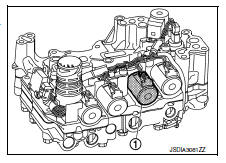
CVT CONTROL SYSTEM : Primary Pressure Solenoid Valve
- The primary pressure solenoid valve
 is installed to control
valve. - The primary pressure solenoid valve controls the primary pressure control valve. For information about the primary pressure control valve, refer to TM-88, "TRANSAXLE : Component Description".
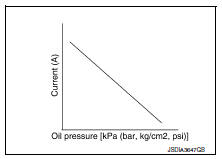
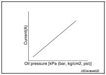
- The primary pressure solenoid valve uses the linear solenoid valve [N/H (normal high) type].
NOTE:
- The principle of the linear solenoid valve utilizes the fact that the force pressing on the valve spool installed inside the coil increases nearly in proportion to the current. This allows it to produce a fluid pressure that is proportional to this pressing force.
- The N/H (normal high) produces hydraulic control when the coil is not energized.
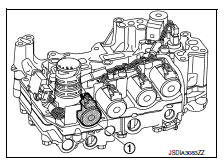
CVT CONTROL SYSTEM : Low Brake Solenoid Valve
- The low brake solenoid valve
 is installed to
control valve. - The low brake solenoid valve adjusts the low brake engaging pressure.
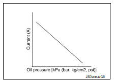
- The torque converter clutch solenoid valve utilizes a linear solenoid valve [N/L (normal low) type].
NOTE:
- The principle of the linear solenoid valve utilizes the fact that the force pressing on the valve spool installed inside the coil increases nearly in proportion to the current. This allows it to produce a fluid pressure that is proportional to this pressing force.
- The N/L (normal low) type does not produce hydraulic control when the coil is not energized.
CVT CONTROL SYSTEM : High Clutch & Reverse Brake Solenoid Valve
- The line pressure solenoid valve
 is
is
installed to control valve. - The line pressure solenoid valve controls the pressure regulator valve. For information about the pressure regulator valve, refer to TM-88, "TRANSAXLE : Component Description".
- The line pressure solenoid valve uses the linear solenoid valve [N/ H (normal high) type].
NOTE:
- The principle of the linear solenoid valve utilizes the fact that the force pressing on the valve spool installed inside the coil increases nearly in proportion to the current. This allows it to produce a fluid pressure that is proportional to this pressing force.
- The N/H (normal high) produces hydraulic control when the coil is not energized.
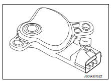
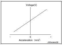
CVT CONTROL SYSTEM : G Sensor
- G sensor is installed to floor under instrument lower cover.
- G sensor detects front/rear G and inclination applied to the vehicle.
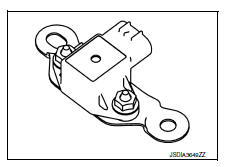
- G sensor converts front/rear G and inclination applied to the vehicle to voltage signal. TCM evaluates front/rear G and inclination angle of the vehicle from the voltage signal.
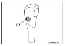
CVT CONTROL SYSTEM : Overdrive Control Switch
- The overdrive control switch is installed to the selector lever knob.
- When the OD OFF indicator lamp on the combination meter is OFF and the overdrive control switch is pressed, the OD OFF is active and the OD OFF indicator lamp is ON.
- When the OD OFF indicator lamp on the combination meter is ON and the overdrive control switch is pressed, the OD OFF is cancelled and the OD OFF indicator lamp is OFF.
CVT CONTROL SYSTEM : OD OFF Indicator Lamp
DESIGN/PURPOSE
The OD OFF indicator lamp notifies the driver that the shift control of transaxle is in OD OFF.
BULB CHECK
For two seconds after the ignition switch is turned ON.
SIGNAL PATH
- When overdrive control switch signal is input to the combination meter, the combination meter transmits the overdrive control switch signal to the TCM via CAN communication.
- When all of the following conditions are satisfied, the TCM transmits OD OFF indicator lamp signal to the combination meter via CAN communication. The combination meter turns ON the OD OFF indicator lamp on the combination meter, according to the signal.
- TCM receives overdrive control switch via CAN communication from combination meter.
- Selector lever: D position.
LIGHTING CONDITION
When all of the following conditions are satisfied.
- Ignition switch: ON
- Selector lever: D position
- Overdrive control switch is pressed when the OD OFF indicator lamp is OFF.
SHUTOFF CONDITION
- When any of the conditions listed below is satisfied.
- Ignition switch: Other than ON
- Overdrive control switch is pressed when the OD OFF indicator lamp is ON.
- Selector lever is shifted to other than D position when the OD OFF indicator lamp is ON.
CVT CONTROL SYSTEM : Shift Position Indicator
PURPOSE
The shift position indicator displays the shift position of transaxle.

SIGNAL PATH
- The TCM judges the shift position by the transmission range switch signal.
- The TCM transmits the shift position signal to the combination meter via CAN communication. The combination meter shows the shift position indicator on the information display, according to the signal.
LIGHTING CONDITION
Ignition switch: ON
SHUTOFF CONDITION
Ignition switch: Other than ON
SHIFT LOCK SYSTEM
SHIFT LOCK SYSTEM : Component Parts Location
COMPONENT DESCRIPTION
| No. | Component | Function |
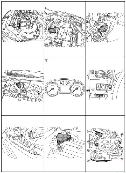
| 1 | Shift lock solenoid | It operates according to the signal from the stop lamp switch and moves the lock lever. |
| 2 | Park position switch | It detects that the selector lever is in “P” position. |
| 3 | Shift lock release button | Forcibly releases the shift lock when pressed. |
| 4 | Stop lamp switch |
|
 Preparation
Special Service Tools
The actual shapes of Kent-Moore tools may differ from those of special
service tools illustrated here.
*: The O-ring as a unit part is set as a SST.
Commercial Service ...
 Structure and operation
TRANSAXLE
TRANSAXLE : Cross-Sectional View
Converter housing
Oil pump
Counter drive gear
Control valve
Oil pan
Primary pulley
Steel belt
Secondary pulley
Planetary gear (auxi ...
Other materials:
Starting system (with intelligent key)
Wiring Diagram
...
Variable voltage control system
CAUTION
Do not ground accessories directly to
the battery terminal. Doing so will bypass
the variable voltage control system
and the vehicle battery may not
charge completely.
Use electrical accessories with the engine
running to avoid discharging the
vehicle battery.
Your v ...
U1010 control unit (can)
Description
Initial diagnosis of combination meter.
Dtc logic
Dtc detection logic
Dtc
Display contents of consult
Detection condition
Possible malfunction
U1010
CONTROL UNIT (CAN)
[U1010]
When detecting error during the initial diagnosis of
the can controlle ...
