Nissan Sentra Service Manual: Structure and operation
TRANSAXLE
TRANSAXLE : Cross-Sectional View
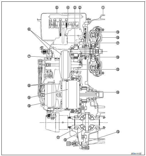
- Converter housing
- Oil pump
- Counter drive gear
- Control valve
- Oil pan
- Primary pulley
- Steel belt
- Secondary pulley
- Planetary gear (auxiliary gearbox)
- Side cover
- Transaxle case
- Differential case
- Final gear
- Reduction gear
- Counter driven gear
- Drive sprocket
- Oil pump chain
- Torque converter
- Driven sprocket
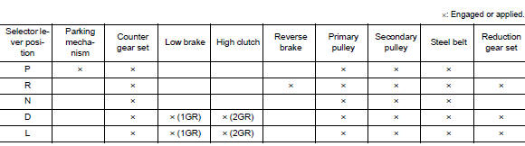
TRANSAXLE : Operation Status
TRANSAXLE : Transaxle Mechanism
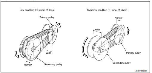
BELT & PULLEY
Mechanism
It is composed of a pair of pulleys (the groove width is changed freely in the axial direction) and the steel belt (the steel plates are placed continuously and the belt is guided with the multilayer steel rings on both sides).
The groove width changes according to wrapping radius of steel belt and pulley from low status to overdrive status continuously with non-step. It is controlled with the oil pressures of primary pulley and secondary pulley.
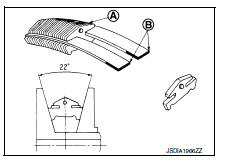
Steel belt
It is composed of multiple steel plates and two steel rings stacked to a several number. The feature of this steel belt transmits power with compression of the steel plate in contrast with transmission of power in pulling with a rubber belt. Friction force is required with the pulley slope to transmit power from the steel plate. The force is generated with the following mechanism: Oil pressure applies to the secondary pulley to nip the plate. ⇒The plate is pushed and extended outward. ⇒The steel ring shows withstands.
⇒Pulling force is generated on the steel ring. ⇒The plate of the primary pulley is nipped between the pulley. ⇒Friction force is generated between the steel belt and the pulley.
Therefore, responsibilities are divided by the steel plate that transmits the power with compression and the steel ring that maintains necessary friction force. In this way, the tension of the steel ring is distributed on the entire surface and stress variation is limited, resulting in good durability.
Pulley
The primary pulley (input shaft side) and the secondary pulley (output shaft side) have the shaft with slope (fixed cone surface), movable sheave (movable cone surface that can move in the axial direction) and oil pressure chamber at the back of the movable sheave.
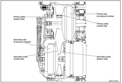
Pulley gear shifting operation
- Pulley gear shifting operation
The movable sheave slides on the shaft to change the groove width of the pulley. Input signals of engine load (accelerator pedal opening), engine revolution and gear ratio (vehicle speed) change the operation pressures of the primary pulley and the secondary pulley, and controls the pulley groove width. Along with change of the pulley groove width, the belt contact radius is changed. This allows continuous and stepless gear shifting from low to overdrive. “The contact radius ratio of each pulley in contact with the belt x auxiliary gearbox gear ratio” is the gear ratio.
AUXILIARY GEARBOX MECHANISM
1st, 2nd and reverse gears are changed with the planetary gear mechanism.
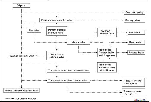
TRANSAXLE : Oil Pressure System
Oil pressure required for operation of the transaxle transmission mechanism is generated by oil pump, oil pressure control valve, solenoid valve, etc.
TRANSAXLE : Component Description
| Part name | Function |
| Torque converter | It is composed of the cover converter, turbine assembly, stator, pump impeller assembly, etc. It increases the engine torque and transmits the power to the transaxle. |
| Oil pump | Through the oil pump drive chain, it uses the vane oil pump driven by the engine. It generates necessary oil pressure to circulate fluid and to operate the clutch and brake. |
| Counter gear set | The power from the torque converter is transmitted to the primary pulley through the counter drive gear and the counter driven gear. |
| Belt & pulley (Continuously variable transmission) | It is composed of the primary pulley, secondary pulley, steel belt, etc. and the mechanism performs shifting, changes the gear ratio and transmits the power with oil pressure from the control valve. |
| Auxiliary gearbox (stepped transmission) | It is composed of the planetary gear, multi-disc clutch, multi-disc brake, etc. and the mechanism performs shifting (1-2 gear shifting and reverse) with oil pressure from the control valve. |
| Reduction gear set | Conveys power from the transmission mechanism to the reduction gear and the final gear. |
| Parking mechanism | When the shift lever is changed to P position, the mechanism fixes the parking gear (integrated with the reduction gear) and the fixes the output shaft |
| Control valve | Controls oil pressure from the oil pump to the pressure suitable for the line pressure control system, shift control system, lock-up control system and lubrication system. |
| Pressure regulator valve | Adjusts the discharge pressure from the oil pump to the optimum pressure (line pressure) corresponding to the driving condition. |
| Torque converter regulator valve | Adjusts the feed pressure to the torque converter to the optimum pressure corresponding to the driving condition. |
| Pilot valve | Adjusts line pressure and produces a constant pressure (pilot pressure) necessary for activating each solenoid valve. |
| Manual valve | Distributes the clutch and brake operation pressures (pilot pressure) corresponding to each shift position. |
| High clutch/reverse brake switching valve | Switches the circuit for the high clutch and the reverse brake. |
| Torque converter clutch control valve | It is operated with the torque converter clutch solenoid valve and it adjusts the tightening pressure and non-tightening pressure of the torque converter clutch piston of the torque converter. |
| Primary pressure control valve | It is operated with the primary pressure solenoid valve and adjusts the feed pressure to the primary pulley. |
| Primary pressure solenoid valve | TM-79, "CVT CONTROL SYSTEM : Primary Pressure Solenoid Valve" |
| Low brake solenoid valve | TM-79, "CVT CONTROL SYSTEM : Low Brake Solenoid Valve" |
| High clutch & reverse brake solenoid valve | TM-80, "CVT CONTROL SYSTEM : High Clutch & Reverse Brake Solenoid Valve" |
| Torque converter clutch solenoid valve | TM-80, "CVT CONTROL SYSTEM : Torque Converter Clutch Solenoid Valve" |
| Line pressure solenoid valve | TM-81, "CVT CONTROL SYSTEM : Line Pressure Solenoid Valve" |
FLUID COOLER & FLUID WARMER SYSTEM
FLUID COOLER & FLUID WARMER SYSTEM :System Description
CVT FLUID COOLER SCHEMATIC
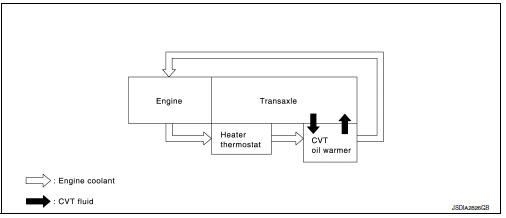
COMPONENT DESCRIPTION
CVT Oil Warmer
- The CVT oil warmer is installed on the front part of transaxle assembly.
- When engine is started while engine and CVT are cold, engine
coolant temperature rises more quickly than CVT fluid temperature.
CVT oil warmer is provided with two circuits for CVT and engine coolant respectively so that warmed engine coolant warms CVT quickly. This helps shorten CVT warming up time, improving fuel economy.
- A cooling effect is obtained when CVT fluid temperature is high.
Heater Thermostat
- The heater thermostat
 is installed to front
part of transaxle assembly. - The heater thermostat open and close with set temperature.
SHIFT LOCK SYSTEM
SHIFT LOCK SYSTEM : System Description
- The shift lock is the mechanism provided to prevent quick start of a vehicle by incorrect operation of a drive when the selector lever is in “P” position.
- Selector lever can be shifted from the “P” position to another position when the following conditions are satisfied.
- Ignition switch is ON.
- Stop lamp switch is ON (brake pedal is depressed)
- Press the selector button.
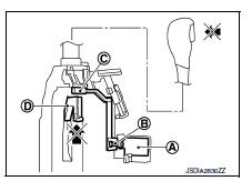
SHIFT LOCK OPERATION AT P POSITION
When brake pedal is not depressed (no selector operation allowed)
When the brake pedal is not depressed with the ignition switch ON,
the shift lock solenoid
 is OFF (not
energized) and the solenoid rod
 is extended
with spring.
The connecting lock lever
 is located at the position
shown in the
figure when the solenoid rod is extended. It prevents the movement
of the detent rod 
. The selector lever cannot be shifted from the “P”
position for this reason.
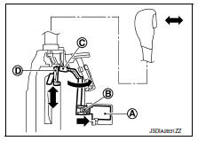
When brake pedal is depressed (selector lever operation allowed)
The shift lock solenoid
is turned ON (energized)
when the brake
pedal is depressed with the ignition switch ON. The solenoid rod
is compressed with the electromagnetic force. The connecting lock
lever
rotates when the solenoid rod is compressed. Therefore, the
detent rod can be moved
. The selector lever can be
shifted to
other positions for this reason.
P POSITION HOLD MECHANISM (IGNITION SWITCH LOCK)
The shift lock solenoid  is not energized when the ignition switch is
in any position other than ON. The shift mechanism is locked and “P”
position is held. The operation cannot be performed from “P” position
if the brake pedal is depressed with the ignition switch ON when the
operation system of shift lock solenoid is malfunctioning. However,
the lock lever 
is forcibly rotated and the shift lock is released when
the shift lock release button
 is pressed from
above. The selector
operation from “P” position can be performed.
 : Detent rod
CAUTION:
Use the shift lock release button only when the selector lever cannot be operated even if the brake pedal is depressed with the ignition switch ON.
KEY LOCK SYSTEM
KEY LOCK SYSTEM : System Description
KEY LOCK MECHANISM
The key is not set to LOCK when the selector lever is not selected to P position. This prevents the key from being removed from the key cylinder.
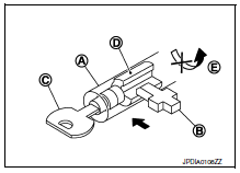
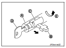
Key lock status
The slider  in the key cylinder
  is moved to the left side of the figure
when the selector lever is in any position other than “P” position.
The rotator  that
that
rotates together with the key cannot be rotated
for this reason. The key cannot be removed from the key cylinder
because it cannot be turned to LOCK
 .
.
Key unlock status
The slider  in the key cylinder
  is moved to the right side of the
figure when the selector lever is in “P” position and the finger is
removed from the selector button. The rotator
 can be
rotated for
this reason. The key  can be removed from the key cylinder
because it can be turned to LOCK  .
.
 System description
Component parts
CVT CONTROL SYSTEM
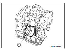
CVT CONTROL SYSTEM : Component Parts Location
No.
Component
Function
1
ECM
Mainly transmits the following signal to TCM via CAN
...
 System
CVT CONTROL SYSTEM
CVT CONTROL SYSTEM : System Diagram
CVT CONTROL SYSTEM : System Description
DESCRIPTION
CVT detects the vehicle driving status from switches, sensors and
signals, a ...
Other materials:
Heated seats (if so equipped)
The front seats are warmed by built-in heaters.
Start the engine.
Push the LO or HI position of the switch, as
desired. The indicator light in the switch will
illuminate.
The heater is controlled by a thermostat,
automatically turning the heater on and off.
The indicator light ...
Symptom diagnosis
Push-button ignition switch does not operate
Description
Check that vehicle is under the condition shown in “Conditions of vehicle”
before starting diagnosis, and check
each symptom.
Note:
The engine start function, door lock function, power distribution system,
and nats-ivis/nvis ...
M&a branch line circuit
Diagnosis procedure
1.Check connector
Turn the ignition switch off.
Disconnect the battery cable from the negative terminal.
Check the terminals and connectors of the combination meter for damage,
bend and loose connection
(unit side and connector side).
Is the inspection result nor ...
