Nissan Sentra Service Manual: System
CVT CONTROL SYSTEM
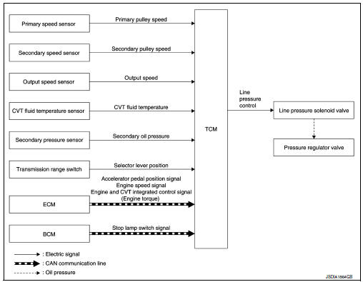
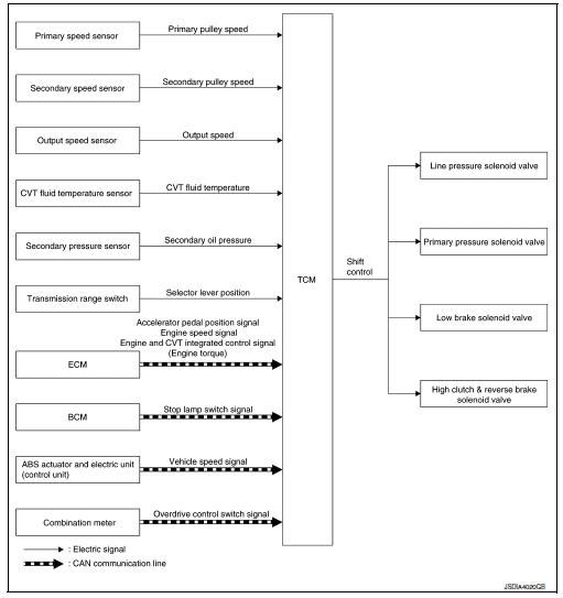
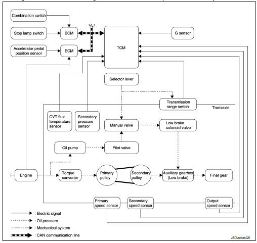
CVT CONTROL SYSTEM : System Diagram
CVT CONTROL SYSTEM : System Description
DESCRIPTION
- CVT detects the vehicle driving status from switches, sensors and signals, and controls the vehicle so that the optimum shift position and shift timing may always be achieved. It also controls the vehicle to reduce shift and lockup shock, etc.
- If a malfunction occurs on the electric system, activate the fail-safe mode only to drive the vehicle.
MAIN CONTROL CONTENTS OF TCM
List of control items and input/output
*: If these input/output signals show errors, TCM activates the fail-safe function.
CVT CONTROL SYSTEM : Fail-Safe
TCM has a fail-safe mode. The mode functions so that operation can be continued even if the signal circuit of the main electronically controlled input/output parts is damaged.
If the vehicle shows following behaviors including “poor acceleration”, a malfunction of the applicable system is detected by TCM and the vehicle may be in a fail-safe mode. At this time, check the DTC code and perform inspection and repair according to the malfunction diagnosis procedures.
Fail-safe function
CVT CONTROL SYSTEM : Protection control
The TCM becomes the protection control status temporarily to protect the safety when the safety of TCM and transmission is lost. It automatically returns to the normal status if the safety is secured.
The TCM has the following protection control.
CONTROL FOR WHEEL SPIN
| Control | When a wheel spin is detected, the engine output and gear ratio are
limited and the line pressure is increased.
At the 1GR, the clutch pressure is increased. |
| Vehicle behavior in control | If the accelerator is kept depressing during wheel spin, the engine revolution and vehicle speed are limited to a certain degree. From the 1GR, upshift to a certain gear ratio is only allowed. |
| Normal return condition | Wheel spin convergence returns the control to the normal control. |
CONTROL WHEN FLUID TEMPERATURE IS HIGH
| Control | When the CVT fluid temperature is high, the gear shift permission maximum revolution and the maximum torque are reduced than usual to prevent increase of the oil temperature. |
| Vehicle behavior in control | Power performance may be lowered, compared to normal control. |
| Normal return condition | The control returns to the normal control when CVT fluid temperature is lowered. |
TORQUE IS REDUCED WHEN DRIVING WITH THE REVERSE GEAR
| Control | Engine output is controlled according to a vehicle speed while reversing the vehicle. |
| Vehicle behavior in control | Power performance may be lowered while reversing the vehicle. |
| Normal return condition | Torque returns to normal by positioning the selector lever in a range other than “R” position. |
REVERSE PROHIBIT CONTROL
| Control | The reverse brake is controlled to avoid becoming engaged when the selector lever is set in “R” position while driving in forward direction at more than the specified speed. |
| Vehicle behavior in control | If the selector lever is put at “R” position when driving with the forward gear, the gear becomes neutral, not reverse. |
| Normal return condition | The control returns to normal control when the vehicle is driven at low speeds. (The reverse brake becomes engaged.) |
Line pressure control
LINE PRESSURE CONTROL : System Description
SYSTEM DIAGRAM
DESCRIPTION
Highly accurate line pressure control (secondary pressure control) reduces friction for improvement of fuel economy.
Normal Oil Pressure Control
Appropriate line pressure (secondary pressure) suitable for driving condition are determined based on the accelerator pedal position, engine speed, primary pulley (input) speed, secondary pulley (output) speed, vehicle speed, input torque, stop lamp switch signal, transmission range switch signal, lock-up signal, power voltage, target shift ratio, oil temperature and oil pressure.
Secondary Pressure Feedback Control
In normal oil pressure control and oil pressure control in shifting, highly accurate secondary pressure is determined by detecting the secondary pressure using an oil pressure sensor and by feedback control.
Shift control
SHIFT CONTROL : System Description
SYSTEM DIAGRAM
DESCRIPTION
To select the gear ratio that can give the driving force to meet driver's intent or vehicle situation, the vehicle driving condition such as vehicle speed or accelerator pedal position is detected and the most appropriate gear ratio is selected and the shifting method before reaching the speed is determined. The information is output to the primary pressure solenoid valve to control the line pressure input/output to the primary pulley, to determine the primary pulley (movable pulley) position and to control the gear position.
D Position (OD ON) Gear shifting is performed in all shifting ranges from the lowest to the highest gear ratio.
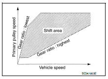
D Position (OD OFF)
The gear ratio is generally high by limiting the shifting range on the high side, and this always generates a large driving power.
L Position
By limiting the shifting range only to the lowest of the gear ratio, a large driving force and engine brake are obtained.
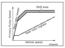
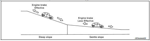
Hill Climbing And Descending Control
If a downhill is detected with the accelerator pedal is released, the system performs downshift to increase the engine brake force so that vehicle may not be accelerated more than necessary. If a climbing hill is detected, the system improves the acceleration performance in re-acceleration by limiting the gear shift range on the high side.
NOTE:
For engine brake control on a downhill, the control can be stopped with CONSULT.
Control In Acceleration
From change of the vehicle speed or accelerator pedal position, the acceleration request level of the driver or driving scene is evaluated. In start or acceleration during driving, the gear shift characteristics with linearity of revolution increase and vehicle speed increase are gained to improve the acceleration feel.
Select control
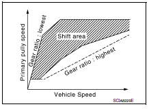
SELECT CONTROL : System Description
SYSTEM DIAGRAM
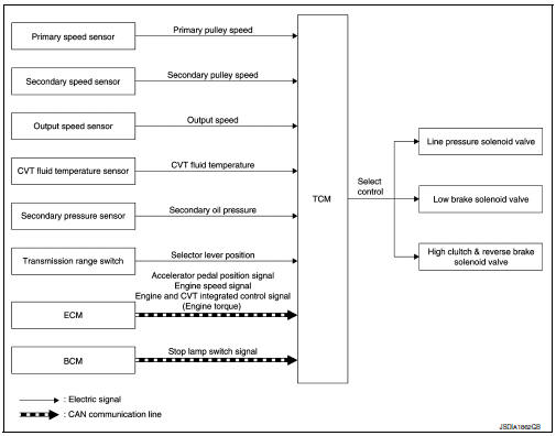
DESCRIPTION
Based on accelerator pedal angle, engine speed, primary pulley speed, and the secondary pulley speed, the optimum operating pressure is set to reduce impact of a selector lever operation while shifting from “N” (“P”) to “D” (“R”) position.
Lock-up control
LOCK-UP CONTROL : System Description
SYSTEM DIAGRAM
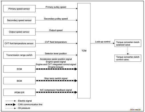
DESCRIPTION
- Controls for improvement of the transmission efficiency by engaging the torque converter clutch in the torque converter and eliminating slip of the converter. Achieves comfortable driving with slip control of the torque converter clutch.
- The oil pressure feed circuit for the torque converter clutch piston chamber is connected to the torque converter clutch control valve. The torque converter clutch control valve is switched by the torque converter clutch solenoid valve with the signal from TCM. This controls the oil pressure circuit, which is supplied to the torque converter clutch piston chamber, to the release side or engagement side.
- If the CVT fluid temperature is low or the vehicle is in fail-safe mode due to malfunction, lock-up control is prohibited.
Lock-up engagement
In lock-up engagement, the torque converter clutch solenoid valve makes the torque converter clutch control valve locked up to generate the lock-up apply pressure. This pushes the torque converter clutch piston for engagement.
Lock-up release condition
In lock-up release, the torque converter clutch solenoid valve makes the torque converter clutch control valve non-locked up to drain the lock-up apply pressure. This does not engage the torque converter clutch piston.
IDLE NEUTRAL CONTROL
Idle neutral control
IDLE NEUTRAL CONTROL : System Description
SYSTEM DIAGRAM
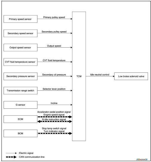
DESCRIPTION
If a driver has no intention of starting the vehicle in D position, TCM operates the low brake solenoid valve and controls the oil pressure of the low brake to be low pressure. Therefore, the low brake is in the release (slip) status and the power transmission route of transaxle is the same status as the N position. In this way, the transaxle is in idling status and load to the engine can be reduced to improve fuel economy.
Idle Neutral Control Start Condition
Idle neutral control is started when all of the following conditions are fulfilled. However, during idle neutral control, idle neutral control is stopped when any of the following conditions is not met.
Driving environment : Flat road or road with mild gradient
Selector lever position : “D” position
Vehicle speed : 0 km/h (0 MPH)
Accelerator pedal position : 0.0/8
Brake pedal : Depressed
Engine speed : Idle speed
Turn signal lamp/hazard signal lamp : Not activated
NOTE:
Stops or prohibits the idle neutral control when the TCM and ECM detect that the vehicle is in one of the following conditions.
- Engine coolant temperature and CVT fluid temperature are the specified temperature or more, or the specified temperature or less.
- When a transaxle malfunction occurs.
- When the vehicle detects DTC and is in
- When idle speed increases due to heavy electric load*.
*: When any one of rear window defogger switch, A/C switch, headlamp, fog lamp is turned ON. In addition, when the steering wheel is operated.
Idle Neutral Control Resume Condition
When the idle neutral control finishes, if the vehicle is driven at more than the specified speed and the idle neutral control start conditions are satisfied, the idle neutral control starts again. If the vehicle has a malfunction, the idle neutral control does not start.
ECO MODE CONTROL
ECO MODE CONTROL : System Description
- Driving mode that selects the shift schedule with priority on fuel economy which gives low engine revolution
- The gear shift line is not changed with the control mode change for the following conditions:
- When the selector lever is at “L” position.
- When the selector lever is at D position and overdrive is OFF.
- For details on ECO mode control, refer to DMS-26, "ECO MODE CONTROL : System Description".
FAIL-SAFE
If a malfunction occurs in the system of CVT during ECO mode, the ECO mode indicator lamp turns OFF and the control switches to the normal mode control.
SPORT MODE CONTROL
SPORT MODE CONTROL : System Description
- Driving mode that keeps high engine revolution and provides direct feel and acceleration performance suitable for driving on winding road.
- The gear shift line is not changed with the control mode change for the following conditions:
- When the selector lever is at “L” position.
- When the selector lever is at D position and overdrive is OFF.
- For details on SPORT mode control, refer to DMS-63, "SPORT MODE CONTROL : System Description".
FAIL-SAFE
If a malfunction occurs in the system of CVT during SPORT mode, the SPORT mode indicator lamp turns OFF and the control switches to the normal mode control.
ON BOARD DIAGNOSTIC (OBD) SYSTEM
Description
This is an onboard diagnosis system which records diagnosis information related to the exhaust gases. It detects malfunctions related to sensors and actuators. The malfunctions are indicated by means of the malfunction indicator lamp (MIL) and are stored as DTC in the ECU memory. The diagnosis information can be checked using a diagnosis tool (GST: Generic Scan Tool).
Function of OBD
The GST is connected to the diagnosis connector on the vehicle and communicates with the on-board control units to perform diagnosis. The diagnosis connector is the same as for CONSULT. Refer to GI-47, "Description".
 Structure and operation
TRANSAXLE
TRANSAXLE : Cross-Sectional View
Converter housing
Oil pump
Counter drive gear
Control valve
Oil pan
Primary pulley
Steel belt
Secondary pulley
Planetary gear (auxi ...
 Diagnosis system (TCM)
DIAGNOSIS DESCRIPTION
DIAGNOSIS DESCRIPTION : 1 Trip Detection Diagnosis and 2 Trip Detection
Diagnosis
NOTE:
“Start the engine and turn OFF the ignition switch after warm-up.” This i ...
Other materials:
Wiring diagram
Eco mode system
Wiring Diagram
...
Instrument panel
Headlight/fog light (if so equipped)/turn
signal switch
Steering wheel switch for trip
computer, audio control and
Bluetooth® Hands-Free Phone System
(if so equipped)
Driver’s supplemental air bag/Horn
Meters and gauges
Cruise control main/set switches
(if so equipped)
...
Basic inspection
Diagnosis and repair workflow
Work Flow (With GR8-1200 NI)
STARTING SYSTEM DIAGNOSIS WITH GR8-1200 NI
To test the starting system, use the following special service tool:
GR8-1200 NI Multitasking battery and electrical diagnostic station
NOTE:
Refer to the diagnostic station Instruction M ...
