Nissan Sentra Service Manual: Diagnosis system (TCM)
DIAGNOSIS DESCRIPTION
DIAGNOSIS DESCRIPTION : 1 Trip Detection Diagnosis and 2 Trip Detection Diagnosis
NOTE:
“Start the engine and turn OFF the ignition switch after warm-up.” This is defined as 1 trip.
- TRIP DETECTION DIAGNOSIS
When initial malfunction is detected, TCM memorizes DTC. In these diagnoses, some illuminate MIL and some do not. Refer to TM-126, "DTC Index".
- TRIP DETECTION DIAGNOSIS
When initial malfunction is detected, TCM memorizes DTC of the 1st trip. MIL does not light at this stage. <1 trip> If the same malfunction is detected again in next driving, TCM memorizes DTC. When DTC is memorized, MIL lights. <2 trip> “Trip” of the “2 trip detection diagnosis” indicates the driving mode that executes self-diagnosis during driving.
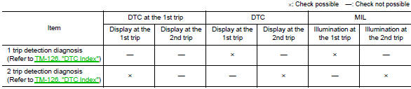
DIAGNOSIS DESCRIPTION : DTC and DTC of 1st Trip
- TRIP DETECTION DIAGNOSIS THAT ILLUMINATES MIL
- The DTC number of the 1st trip is the same as the DTC number.
- When a malfunction is detected at the 1st trip, TCM memorizes DTC of the 1st trip. MIL does not light at this stage. If the same malfunction is not detected at the 2nd trip (conforming to necessary driving conditions), DTC at the 1st trip is erased from TCM. If the same malfunction is detected at the 2nd trip, TCM memorizes DTC and MIL lights at the same time.
- The DTC of the 1st trip is specified in Service $01 of SAE J1979/ISO 15031-5. Since detection of DTC at the 1st trip does not illuminate MIL, warning for a problem is not given to a driver
- For procedure to delete DTC and 1st trip DTC from TCM, refer to TM-108, "CONSULT Function".
- If DTC of the 1st trip is detected, it is necessary to check the cause according to the “Diagnosis flow”. Refer to TM-139, "Work Flow".
DIAGNOSIS DESCRIPTION : Malfunction Indicator Lamp (MIL)
- TCM not only detects DTC, but also sends the MIL signal to ECM through CAN communication. ECM sends the MIL signal to the combination meter through CAN communication according to the signal, and illuminates MIL.
- For malfunction indicator lamp (MIL) description, refer to EC-63, "DIAGNOSIS DESCRIPTION : Malfunction Indicator Lamp (MIL)".
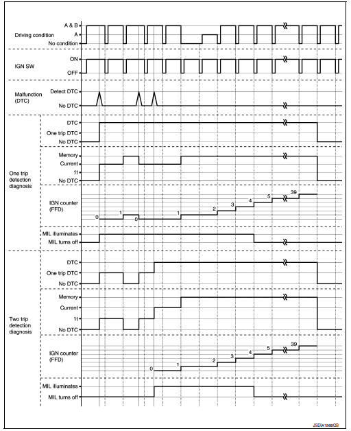
DIAGNOSIS DESCRIPTION : Counter System
RELATION BETWEEN DTC AT 1ST TRIP/DTC/MIL AND DRIVING CONDITIONS (FOR 2 TRIP DETECTION DIAGNOSIS THAT ILLUMINATES MIL)
- When initial malfunction is detected, TCM memorizes DTC of the 1st trip. MIL does not light at this stage.
- If the same malfunction is detected at the 2nd trip, TCM memorizes DTC and MIL lights at the same time.
- Then, MIL goes after driving the vehicle for 3 trips under “Driving condition B” without malfunction.
- DTC is displayed until 40 trips of “Driving condition A” are satisfied
without detecting the same malfunction.
DTC is erased when 40 trips are satisfied.
- When the self-diagnosis result is acceptable at the 2nd trip (conforming to driving condition B), DTC of the 1st trip is erased.
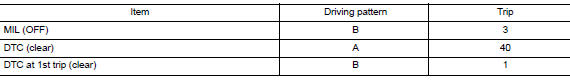
COUNTER SYSTEM LIST
DRIVING CONDITION
Driving pattern A
Driving pattern A is the driving condition that provides warm-up.
In specific, count-up is performed when all of the following conditions are satisfied.
- Engine speed is 400 rpm or more.
- After start of the engine, the water temperature increased by 20В°C (36В°F) or more.
- Water temperature was 70В°C (158В°F) or more.
- The ignition switch was changed from ON to OFF.
NOTE:
- If the same malfunction is detected regardless of the driving condition, reset the A counter.
- When the above is satisfied without detecting the same malfunction, count up the A counter.
- When MIL goes off due to the malfunction and the A counter reaches 40, the DTC is erased.
Driving pattern B
Driving pattern B is the driving condition that performs all diagnoses once.
In specific, count-up is performed when all of the following conditions are satisfied.
- Engine speed is 400 rpm or more.
- Water temperature was 70В°C (158В°F) or more
- In closed loop control, vehicle speed of 70 – 120 km/h (43 – 75 MPH) continued for 60 seconds or more.
- In closed loop control, vehicle speed of 30 – 60 km/h (19 – 37 MPH) continued for 10 seconds or more.
- In closed loop control, vehicle speed of 4 km/h (2 MPH) or less and idle determination ON continued for 12 seconds or more.
- After start of the engine, 22 minutes or more have passed.
- The condition that the vehicle speed is 10km/h (6 MPH) or more continued for 10 seconds or more in total.
- The ignition switch was changed from ON to OFF
NOTE:
- If the same malfunction is detected regardless of the driving condition, reset the B counter.
- When the above is satisfied without detecting the same malfunction, count up the B counter.
- When the B counter reaches 3 without malfunction, MIL goes off
- When the B counter is counted once without detecting the same malfunction after TCM memorizes DTC of the 1st trip, DTC of the 1st trip is erased.
TIME CHART
CONSULT Function
APPLICABLE ITEM
| Conditions | Function |
| All DTC Reading | Display all DTCs or diagnostic items that all ECUs are recording and judging. |
| Work Support | This mode enables a technician to adjust some devices faster and more accurately. |
| Self Diagnostic Results | Retrieve DTC from ECU and display diagnostic items. |
| Data Monitor | Monitor the input/output signal of the control unit in real time. |
| CAN Diagnosis | This mode displays a network diagnosis result about CAN by a diagram. |
| CAN Diagnosis Support Monitor | It monitors the status of CAN communication. |
| ECU Identification | Display the ECU identification number (part number etc.) of the selected system. |
| CALIB DATA | The calibration data status of TCM can be checked. |
SELF DIAGNOSTIC RESULTS
Refer to TM-126, "DTC Index".
DTC at 1st trip and method to read DTC
- DTC (P0705, P0711, P0720, etc.) is specified by SAE J2012/ISO 15031-6.
- DTC and DTC at 1st trip are displayed on “Self Diagnostic results” of
CONSULT.
When DTC is currently detected, “CRNT” is displayed. If “PAST” is displayed, it shows a malfunction occurred in the past. The trip number of drive without malfunction of concerned DTC can be confirmed with “IGN counter” inside “FFD”.
- When the DTC at the 1st trip is detected, the “timing” is displayed as “1t”.
DTC deletion method
NOTE:
- If the battery terminal is disconnected, the TCM memory is erased. (The disconnection time varies from several seconds to several hours
- If the ignition switch is left ON after repair, turn OFF the ignition
switch and wait for 10 seconds or more.
Then, turn the ignition ON again. (Engine stop)
- Touch “TRANSMISSION” of CONSULT.
- Touch “Self Diagnostic Result”.
- Touch “Erase”. (DTC memorized in TCM is erased.)
IGN counter
The ignition counter is displayed in “FFD” and the number of times of satisfied “Driving pattern A” is displayed after normal recovery of DTC. Refer to TM-106, "DIAGNOSIS DESCRIPTION : Counter System".
- If malfunction (DTC) is currently detected, “0” is displayed.
- After normal recovery, every time “Driving pattern A” is satisfied, the display value increases from 1 → 2 → 3...38 → 39.
- When MIL turns OFF due to the malfunction and the counter reaches 40, the DTC is erased.
NOTE:
The counter display of “40” cannot be checked.
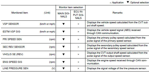
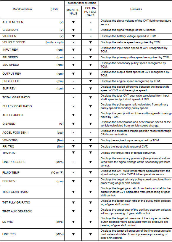
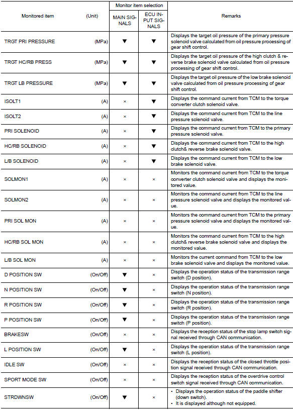
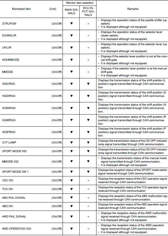
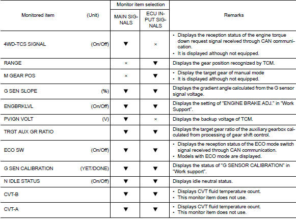
Data monitor
NOTE:
The following table includes information (items) inapplicable to this vehicle. For information (items) applicable to this vehicle, refer to CONSULT display items.
WORK SUPPORT
| Item name | Description |
| ENGINE BRAKE ADJ. | Although there is no malfunction on the transaxle and the CVT system, if a customer make a complaint like “I do not feel comfortable with automatic operation of the engine brake on downhill”, the engine brake may be cancelled with “engine brake adjustment”. |
| CONFORM CVTF DETERIORTN | Check the degradation level of the CVT fluid under severe conditions. |
| G SENSOR CALIBRATION | Compensate the G sensor. |
| ERASE CALIBRATION DATA | Erase the calibration data memorized by TCM. |
| ERASE LEARNING VALUE | Erase the learning value memorized by TCM. |
| ERASE MEMORY DATA | Perform “erasing of the calibration data” and “erasing of the learned value” at the same time. |
Engine brake adjustment
ENGINE BRAKE LEVEL
ON : Turn ON the engine brake control.
OFF : Turn OFF the engine brake control.
Check the degradation level of the CVT fluid.
CVTF degradation level data
210,000 or more : Replacement of the CVT fluid is required.
Less than 210,000 : Replacement of the CVT fluid is not required.
 System
CVT CONTROL SYSTEM
CVT CONTROL SYSTEM : System Diagram
CVT CONTROL SYSTEM : System Description
DESCRIPTION
CVT detects the vehicle driving status from switches, sensors and
signals, a ...
 ECU diagnosis information
TCM
Reference Value
CONSULT DATA MONITOR STANDARD VALUE
NOTE:
The following table includes information (items) inapplicable to this
vehicle. For information (items) applicable
to this veh ...
Other materials:
Differential side oil seal
Exploded View
Transaxle assembly
Differential side oil seal (left side)
Differential side oil seal (right side)
: Vehicle front
: Always replace after every
disassembly.
: Genuine NISSAN CVT Fluid NS-3
Removal and Installation
REMOVAL
NOTE:
Cap or plug openings to prevent f ...
Recommended fluids and lubricants
Fluids and lubricants
*1: For additional information, see “engine oil recommendation”.
*2: As an alternative to this recommended oil, sae 5w-30 conventional
petroleum based oil may be used and meet all specifications
and requirements necessary to maintain the new vehicle limited ...
General maintenance
Explanation of general maintenance
General maintenance includes those items which should be checked during the
normal day-to-day operation
of the vehicle. They are essential if the vehicle is to continue operating
properly. The owners can perform
checks and inspections themselves or have thei ...
