Nissan Sentra Service Manual: ECU diagnosis information
TCM
Reference Value
CONSULT DATA MONITOR STANDARD VALUE
NOTE:
- The following table includes information (items) inapplicable to this vehicle. For information (items) applicable to this vehicle, refer to CONSULT display items.
- In CONSULT, electric shift timing or lock-up timing, i.e. operation
timing of each solenoid valve, is displayed.
Therefore, if there is an obvious difference between the shift timing estimated from a shift shock (or engine speed variations) and that shown on the CONSULT, the mechanism parts (including the hydraulic circuit) excluding the solenoids and sensors may be malfunctioning. In this case, check the mechanical parts following the appropriate diagnosis procedure.
- Shift point (gear position) displayed on CONSULT slightly differs
from shift pattern described in Service Manual.
This is due to the following reasons.
- Actual shift pattern may vary slightly within specified tolerances.
- While shift pattern described in Service Manual indicates start of each shift, CONSULT shows gear position at end of shift.
- The solenoid display (ON/OFF) on CONSULT is changed at the start of gear shifting. In contrast, the gear position display is changed at the time when gear shifting calculated in the control unit is completed.
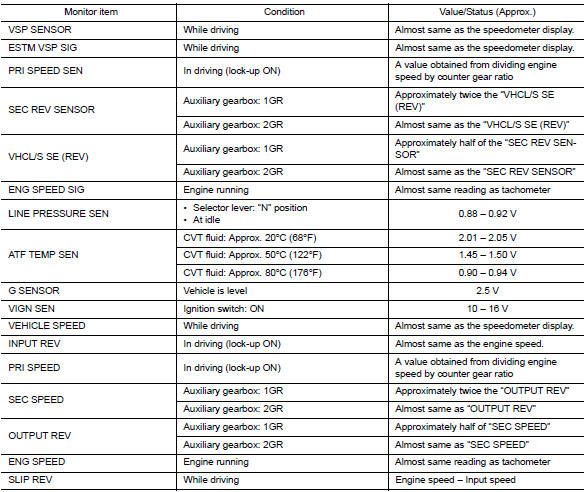
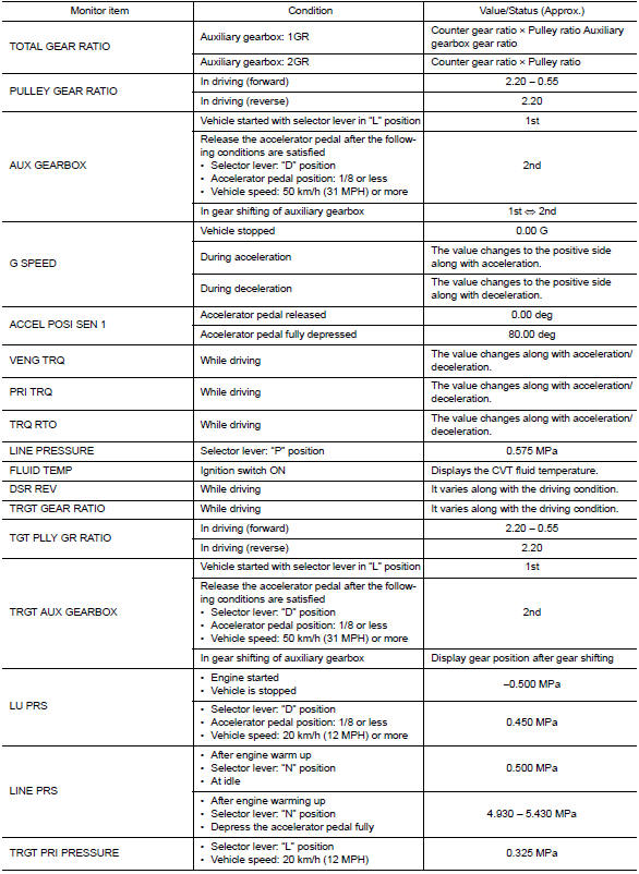
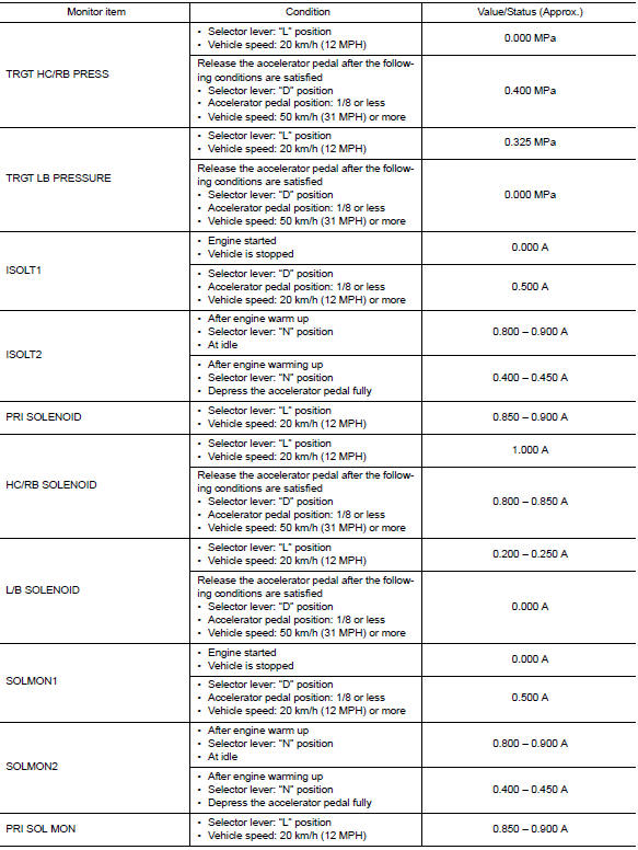
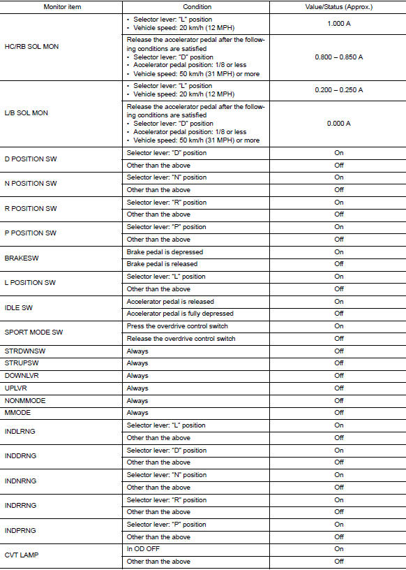
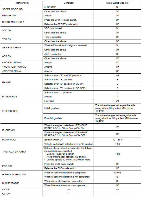
*: This monitor item does not use.
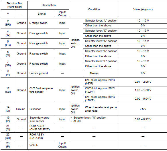
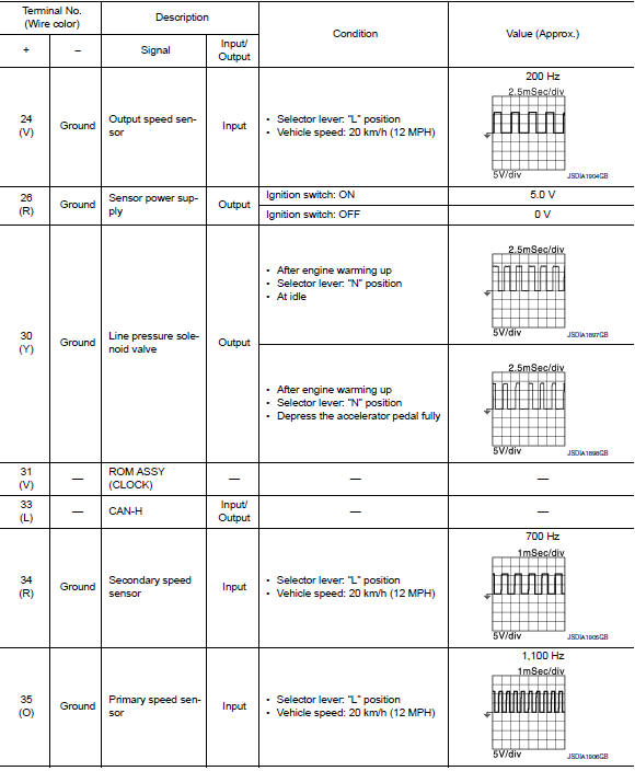
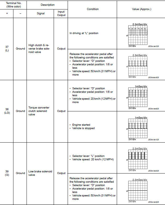
Terminal layout

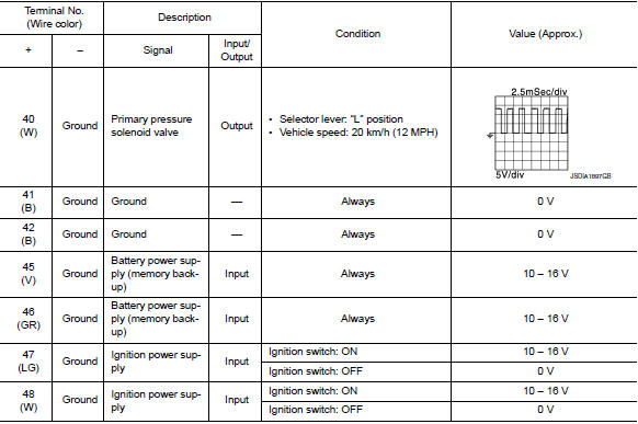
Input/output signal standard
Fail-Safe
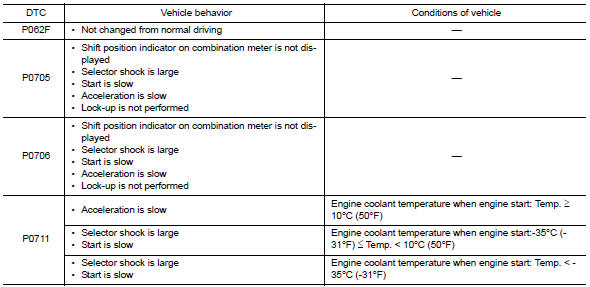
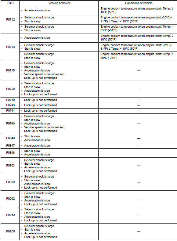
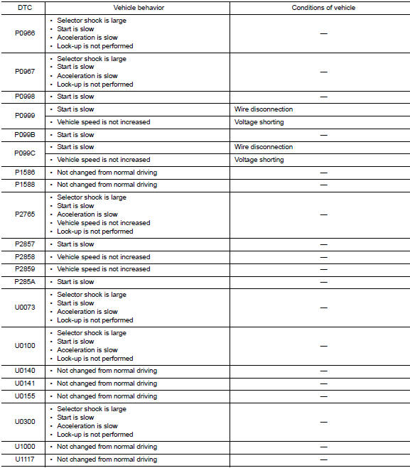
Tcm has a fail-safe mode. The mode functions so that operation can be continued even if the signal circuit of the main electronically controlled input/output parts is damaged.
If the vehicle shows following behaviors including “poor acceleration”, a malfunction of the applicable system is detected by tcm and the vehicle may be in a fail-safe mode. At this time, check the dtc code and perform inspection and repair according to the malfunction diagnosis procedures.
Fail-safe function
Protection control
The tcm becomes the protection control status temporarily to protect the safety when the safety of tcm and transmission is lost. It automatically returns to the normal status if the safety is secured.
The tcm has the following protection control.
CONTROL FOR WHEEL SPIN
| Control | When a wheel spin is detected, the engine output and gear ratio are
limited and the line pressure is increased.
At the 1gr, the clutch pressure is increased. |
| Vehicle behavior in control | If the accelerator is kept depressing during wheel spin, the engine revolution and vehicle speed are limited to a certain degree. From the 1gr, upshift to a certain gear ratio is only allowed. |
| Normal return condition | Wheel spin convergence returns the control to the normal control.V |
Control when fluid temperature is high
| Control | When the cvt fluid temperature is high, the gear shift permission maximum revolution and the maximum torque are reduced than usual to prevent increase of the oil temperature. |
| Vehicle behavior in control | Power performance may be lowered, compared to normal control. |
| Normal return condition | The control returns to the normal control when CVT fluid temperature is lowered. |
Torque is reduced when driving with the reverse gear
| Control | Engine output is controlled according to a vehicle speed while reversing the vehicle. |
| Vehicle behavior in control | Power performance may be lowered while reversing the vehicle. |
| Normal return condition | Torque returns to normal by positioning the selector lever in a range other than “R” position. |
Reverse prohibit control
| Control | The reverse brake is controlled to avoid becoming engaged when the selector lever is set in “r” position while driving in forward direction at more than the specified speed. |
| Vehicle behavior in control | If the selector lever is put at “r” position when driving with the forward gear, the gear becomes neutral, not reverse. |
| Normal return condition | The control returns to normal control when the vehicle is driven at low speeds. (The reverse brake becomes engaged.) |
DTC Inspection Priority Chart
If multiple malfunction codes are detected at the same time, check each code according to the dtc check priority list below.


DTC Index
Note:
- If multiple malfunction codes are detected at the same time, check each code according to the “dtc check priority list”. Tm-125, "dtc inspection priority chart".
- The ignition counter is displayed in “ffd”. Refer to tm-108, "consult function".

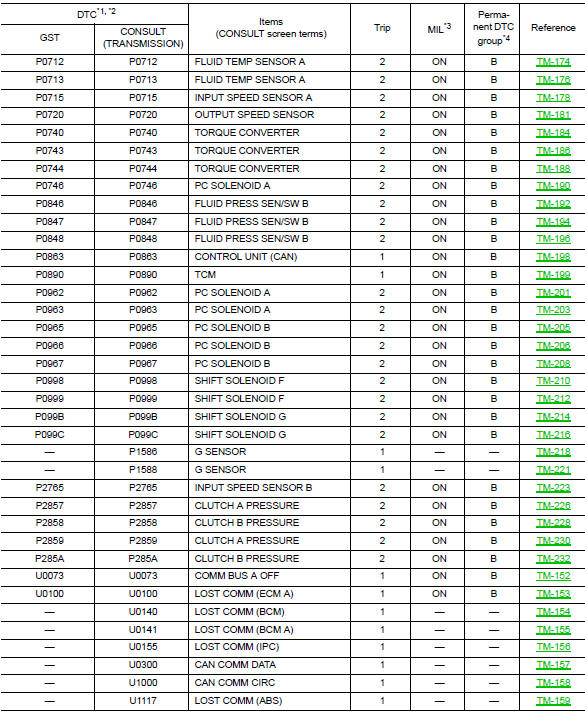
*1: These numbers are specified by sae j2012/iso 15031-6.
*2: The dtc number of the 1st trip is the same as the dtc number.
*3: Refer to tm-106, "diagnosis description : malfunction indicator lamp (mil)".
*4: Refer to tm-151, "description".
 Diagnosis system (TCM)
DIAGNOSIS DESCRIPTION
DIAGNOSIS DESCRIPTION : 1 Trip Detection Diagnosis and 2 Trip Detection
Diagnosis
NOTE:
“Start the engine and turn OFF the ignition switch after warm-up.” This i ...
 Wiring diagram
CVT Control system
Wiring Diagram
CVT Shift lock system
Wiring Diagram
...
Other materials:
How to use this manual
Description
This volume explains “Removal, Disassembly, Installation, Inspection and
Adjustment” and “Trouble Diagnoses”.
Terms
The captions WARNING and CAUTION warn you of steps that must be followed
to prevent personal injury
and/or damage to some part of the vehi ...
C1606 EPS Motor
DTC Logic
DTC DETECTION LOGIC
Dtc
Display item
Malfunction detected condition
Possible cause
C1606
EPS MOTOR
When the motor driver malfunction of EPS control
unit or EPS motor malfunction is detected.
Harness or connector
EPS motor
Eps control ...
Starting system (without intelligent key)
Wiring Diagram
...
