Nissan Sentra B18 (2020-2025) Service Manual: Description
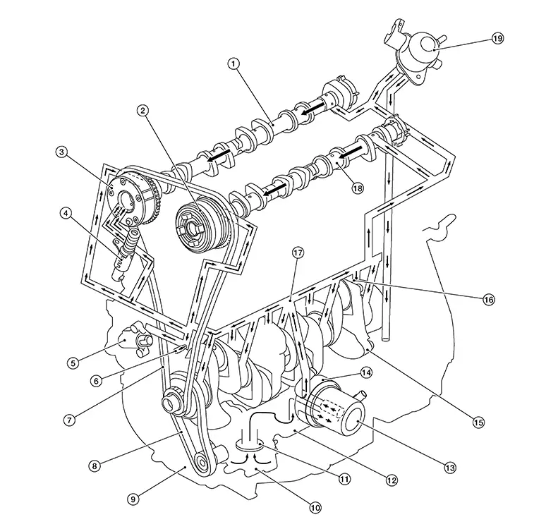
Engine Lubrication System
|
1. |
Camshaft (EXH) |
2. |
Camshaft sprocket (INT) |
3. |
Camshaft sprocket (EXH) |
|
4. |
Exhaust valve timing control solenoid valve |
5. |
Timing chain tensioner |
6. |
Timing chain oil jet |
|
7. |
Timing chain |
8. |
Oil pump drive chain |
9. |
Oil pan |
|
10. |
Oil pump |
11. |
Oil strainer |
12. |
Balancer unit |
|
13. |
Oil filter |
14. |
Oil cooler |
15. |
Crankshaft |
|
16. |
Piston oil jet |
17. |
Main gallery |
18. |
Camshaft (INT) |
|
19. |
High pressure fuel pump |
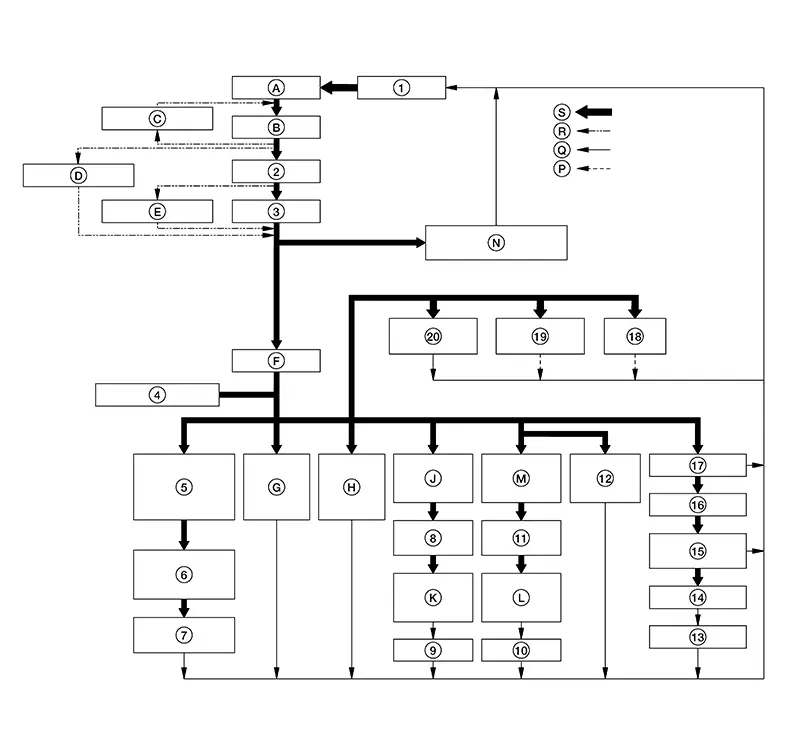
Engine Lubrication System Schematic
|
1. |
Oil pan |
2. |
Oil cooler |
3. |
Oil filter |
|
4. |
Engine oil pressure sensor |
5. |
Exhaust valve timing control solenoid valve oil filter |
6. |
Exhaust valve timing control solenoid valve |
|
7. |
Exhaust valve timing controller |
8. |
Camshaft (INT) |
9. |
Valve lifter (INT) |
|
10. |
Valve lifter (EXH) |
11. |
Camshaft (EXH) |
12. |
High pressure fuel pump |
|
13. |
Piston |
14. |
Connecting rod |
15. |
Connecting rod bearing |
|
16. |
Crankshaft |
17. |
Main bearing |
18. |
Piston oil jet |
|
19. |
Timing chain oil jet |
20. |
Timing chain tensioner |
A. |
Oil strainer |
|
B. |
Oil pump |
C. |
Regulator valve |
D. |
Relief valve |
|
E. |
Relief valve |
F. |
Main gallery |
G. |
Camshaft journal [INT (No. 1)] |
|
H. |
Camshaft journal [EXH (No.1)] |
J. |
Camshaft journal [INT (No. 5)] |
K. |
Camshaft journal (INT) |
|
L. |
Camshaft journal (EXH) |
M. |
Camshaft journal [EXH (No. 6)] |
N. |
Balancer unit [Built in oil pan (upper)] |
|
P. |
Oil injection |
Q. |
To oil pan. Refer to Exploded View. |
R. |
By-pass passage |
|
S. |
Oil passage |


Other materials:
8ch Can Gateway
Removal and Installation
Removal and Installation
CAUTION:
If replacing 8CH CAN gateway, Perform "ADDITIONAL
SERVICE WHEN REPLACING 8CH CAN GATEWAY". Refer to Work Procedure.
REMOVAL
Remove
instrument panel assembly. Refer to Removal and Installation.
Remove side ...
Washer fluid level switch circuit
Description
Transmits the washer level switch signal to the combination meter.
Diagnosis procedure
Regarding Wiring Diagram information, refer to MWI-28, "Wiring Diagram".
1.Check washer level switch signal circuit
Turn ignition switch off.
Disconnect combination meter connecto ...
Cup holders
CAUTION
Avoid abrupt starting and braking when
the cup holder is being used to prevent
spilling the drink. If the liquid is hot, it
can scald you or your passenger.
Use only soft cups in the cup holder.
Hard objects can injure you in an
accident.
Do not use bottle holder for any ...
