Nissan Sentra Service Manual: Washer fluid level switch circuit
Description
Transmits the washer level switch signal to the combination meter.
Diagnosis procedure
Regarding Wiring Diagram information, refer to MWI-28, "Wiring Diagram".
1.Check washer level switch signal circuit
- Turn ignition switch off.
- Disconnect combination meter connector and washer fluid level switch connector.
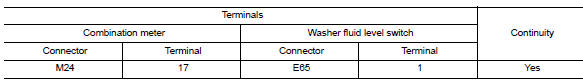
- Check continuity between combination meter harness connector and washer fluid level switch harness connector.
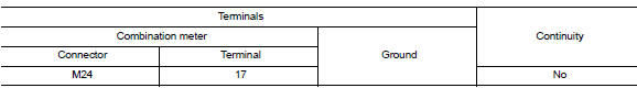
- Check continuity between combination meter harness connector and ground.
Is the inspection result normal? YES >> GO TO 2.
NO >> Repair or replace harness or connector.
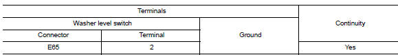
2.Check washer fluid level switch ground circuit
Check continuity between washer fluid level switch connector and ground.
Is the inspection result normal? YES >> Inspection End.
NO >> Repair or replace harness or connector.
Component inspection
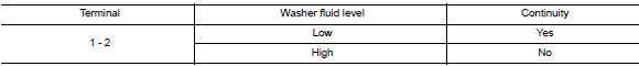
1.Check washer fluid level switch
Check continuity between washer fluid level switch terminals 1 and 2.
Is the inspection result normal?
Yes >> inspection end.
No >> replace washer fluid level switch.Refer to ww-53, "removal and installation".
 A/c auto amp. Connection recognition signal circuit
Description
A/c auto amp. Transmits the a/c auto amp. Connection recognition signal to
the combination meter
Diagnosis procedure (with manual a/c)
Regarding wiring diagram information, refer to ...

Other materials:
Component parts
Component Parts Location
EPS control unit (view with steering
column removed from vehicle)
EPS motor (view with steering column
removed from vehicle)
Torque sensor (view with steering
column removed from vehicle)
ABS actuator and electric unit (control
unit)
EC ...
P0139 HO2S2
DTC Logic
DTC DETECTION LOGIC
The heated oxygen sensor 2 has a much longer switching time
between rich and lean than the air fuel ratio (A/F) sensor 1. The oxygen
storage capacity of the three way catalyst 1 causes the longer
switching time. To judge the malfunctions of heated oxygen sensor
2, ...
System description
Component parts
Component parts location
Ipdm e/r
System
Relay control system
Relay control system : system diagram
Relay control system : system description
Description
IPDM E/R activates the internal control circuit to perform the relay ON-OFF
control according to the input ...
