Nissan Sentra Service Manual: CSC(concentric slave cylinder)
Exploded View
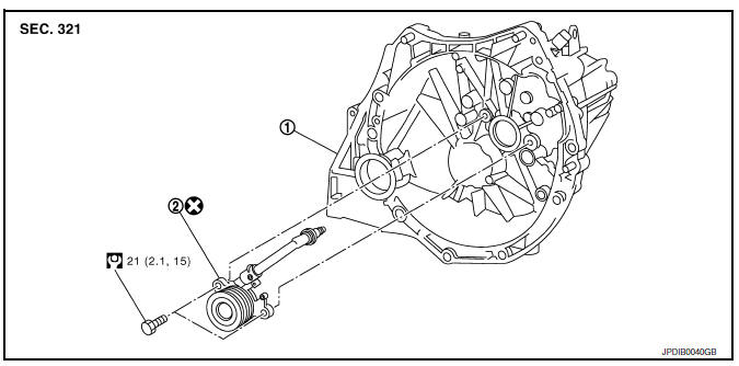
- Transaxle assembly
- CSC (Concentric Slave Cylinder)
Removal and Installation
CAUTION:
- Do not reuse CSC (Concentric Slave Cylinder). The CSC slides back to the original position every time the transaxle assembly is removed. This action may allow dust or contaminants to gather on the sliding parts and damage a seal of CSC causing clutch fluid leakage.
- Do not disassemble CSC.
- Keep painted surface on the body or other parts free of clutch fluid. If clutch fluid spills, wipe up immediately and wash the affected area with water.
REMOVAL
- Remove engine and transaxle assembly. Refer to TM-28, "Removal and Installation".
- Remove CSC bolts, then remove the CSC from transaxle assembly
INSTALLATION
- Install CSC to transaxle assembly, then tighten CSC bolts to the specified torque.
CAUTION:
- Do not reuse CSC.
- Do not install then operate CSC immediately, the piston and stopper of CSC components may fall off.
- Install engine and transaxle assembly in the reverse order of removal. Refer to TM-28, "Removal and Installation".
Inspection and Adjustment
INSPECTION AFTER INSTALLATION
Check for fluid leakage and the fluid level. Refer CL-7, "Inspection".
ADJUSTMENT AFTER INSTALLATION
Perform the air bleeding. Refer to CL-9, "Air Bleeding".
 Clutch piping
Exploded View
CSC (Concentric Slave Cylinder)
Clip
Clutch tube
Clutch damper
Bracket
Clutch master cylinder
Hydraulic Layout
Clutch tube
Lock pin
CSC (Concentric Slav ...
 Clutch disc and clutch cover
Exploded View
Flywheel
Clutch disc
Clutch cover
Input shaft
First step
Final step
Apply lithium-based grease
including molybdenum disulphide.
Removal and Installation
CAU ...
Other materials:
Symptom diagnosis
Audio system
Symptom table
Related to audio
Related to hands-free phone
Before performing diagnosis, confirm that the cellular phone being used
by the customer is compatible with
the vehicle.
It is possible that a malfunction is occurring due to a version change
of the p ...
Warning/indicator lights
Warning
light
Name
Anti-lock Braking
System (ABS) warning
light
Brake warning light
Charge warning light
Door open warning
light
Engine oil pressure
warning light
Low fuel ...
P1800 Intake manifold tuning valve
DTC Logic
DTC DETECTION LOGIC
DTC No.
CONSULT screen terms
(Trouble diagnosis content)
DTC detecting condition
Possible cause
P1800
VIAS S/V-1
(Variable intake air system control
solenoid valve-1)
An excessively low or high voltage signal
is sent to ECM t ...
