Nissan Sentra B18 (2020-2025) Service Manual: Control Valve
Exploded View
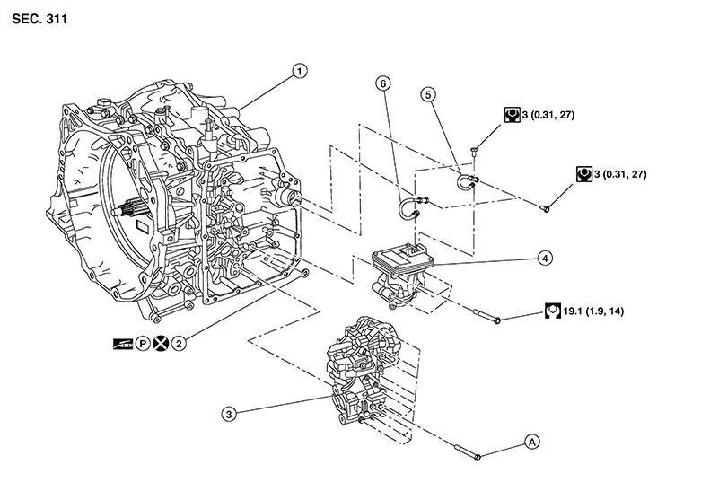
Exploded View
|
1. |
Transaxle assembly |
2. |
Electric oil pump gasket |
3. |
Control valve |
|
4. |
Electric oil pump |
5. |
Terminal assembly (black) |
6. |
Terminal assembly (red) |
|
A |
Refer to Removal and Installation. |
Removal and Installation
Removal and Installation
REMOVAL
Disconnect battery negative terminal. Refer to Battery Disconnect.
Remove the control valve cover. Refer to Removal and Installation.
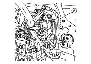
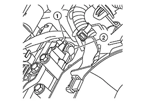
Disconnect the harness connector
(A) from the control valve and route the wire from the control valve.
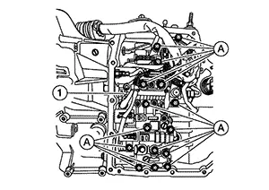
Remove the control valve bolts (A),
and then remove the control valve (1).
CAUTION:
Do not drop the control valve.
INSTALLATION
CAUTION:
-
Do not drop the control valve.
-
Ensure the harness is correctly routed and does not get pinched.
Before installing the control valve
(1), push the shaft (2) inward fully, then rotate the manual lever
(3) as shown.
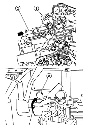
Position the control valve to the
transaxle and verify the shaft (1) and manual lever (2) align as shown.
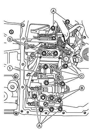
Loosely install the bolts (A,B,C,D)
in the correct location as shown, then tighten to the specified torque.
|
Bolt |
Bolt length mm (in) |
Number of bolt |
|---|---|---|
|
A |
68 (2.68) |
6 |
|
B |
76 (2.99) |
2 |
|
C |
87 (3.43) |
4 |
|
D |
94 (3.70) |
3 |
|
Control valve bolts |
: 7.9 N·m (0.81 kg-m, 70 in-lb) |
CAUTION:
-
There are 4 types of bolts for control valve installation. Install the bolts in the correct locations.
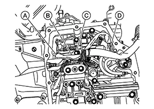
Route the harness (B) through the
notch (A) in the control valve, then under the bolt (C). Install the
connector (D).
Instal the control valve cover. Refer to Removal and Installation.
Perform CVT fluid refill. Refer to Refilling.
Perform "ADDITIONAL SERVICE WHEN REPLACING CONTROL VALVE." Refer to Description.
Inspection and Adjustment
Inspection and Adjustment
INSPECTION AFTER REMOVAL
Check control valve cover for foreign material.
-
If a large amount of worn material is found, clutch plate may be worn.
-
If iron powder is found, bearings, gears, or clutch plates may be worn.
-
If aluminum powder is found, bushing may be worn, or chips or burrs of aluminum casting parts may enter.
Check points where wear is found in all cases.
INSPECTION AFTER INSTALLATION
Check the CVT fluid level and leakage. Refer to Inspection.
ADJUSTMENT AFTER INSTALLATION
Perform "ADDITIONAL SERVICE WHEN REPLACING CONTROL VALVE." Refer to Description.
Other materials:
Trunk Lid Opener Actuator
Component Function Check
Component Function Check
CHECK FUNCTION
CONSULT
Select "Trunk/back door" in "Active Test" mode of
"BCM(TRUNK)".
Select “On” to check tha ...
B1019 Occupant Sens
Dtc Description
DTC Description
DESCRIPTION
B1019 OCCUPANT SENS
The OCS control unit is wired to the air bag
diagnosis sensor unit. The air bag diagnosis sensor unit will
monitor the OCS for failures and interruptions in communication
between the OCS control unit and the air bag ...
B1036-16 Ignition Voltage
Dtc Description
DTC Description
DTC DETECTION LOGIC
DTC No.
CONSULT screen items
(Trouble diagnosis
content)
DTC Detection Condition
...