Nissan Sentra B18 (2020-2025) Service Manual: Electric Oil Pump
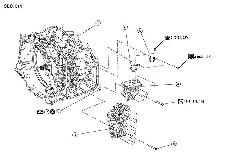
Exploded View
Exploded View
|
1. |
Transaxle assembly |
2. |
Electric oil pump gasket |
3. |
Control valve |
|
4. |
Electric oil pump |
5. |
Terminal assembly (black) |
6. |
Terminal assembly (red) |
|
A. |
Refer to Removal and Installation. |
Removal and Installation
Removal and Installation
REMOVAL
CAUTION:
Perform when the engine is cold.
Note:
When removing components such as hoses, tubes/lines, etc., cap or plug openings to prevent fluid/coolant from spilling.
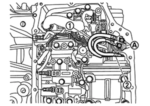
Remove control valve cover. Refer to Removal and Installation.
Remove bolts (A) and bolts (B),
then lower the electric oil pump (1) slightly to access the harness
connector on top. 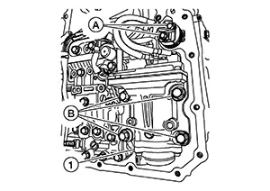
CAUTION:
During removal, note the positions of the Red and Black terminals in order to install properly.
Disconnect the harness connector
(A) then remove the electric oil pump (1). 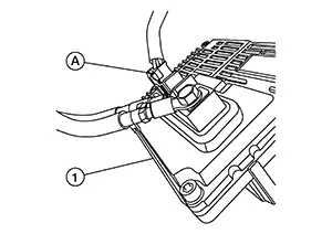
Remove the electric oil pump gasket
(1). 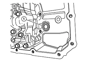
CAUTION:
Do not reuse electric oil pump gasket.
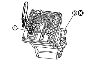
Remove the bolts (A) and remove
the terminals (1) from the electric oil pump (2). 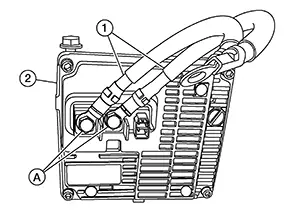
CAUTION:
During removal, note the positions of the Red and Black terminals in order to install properly.
INSTALLATION
Note the following and installation is in the reverse order of removal.
CAUTION:
Do not reuse electric oil pump gasket.
Apply petroleum jelly to the electric oil pump gasket.
-
Install the electric oil pump with following procedure:
-
Install the terminals [black (1)] and [red (2)], to electric oil pump (3). Tighten the bolts (A) to the specified torque. Refer to Exploded View.
CAUTION:
-
Do not reuse the electric oil pump.
-
Connect the electric oil pump terminals as shown.
-
Never install terminals in the opposite direction.
-
Use the plates (B) as the stopper of the terminals when tightening the bolts.
-
Install the terminals with the crimped part facing up.
-
-
Install the connector at top of electric oil pump, then Install it to the transaxle . Install the bolts and tighten to the specified torque . Refer to Exploded View.
-
Install the terminals [red (1)] and [black (2)], to terminal connector. Tighten bolts (A) to the specified torque. Refer to Exploded View.
CAUTION:
-
Never install terminals in the opposite direction.
-
When tightening the bolts, hold the terminal connector by hand to prevent it from rotating, and be careful not to damage the terminal connector body and its O-ring.
-
Other materials:
Unit Disassembly and Assembly
Rear Combination Lamp (body Side)
Exploded View
Exploded View
1.
Rear combination lamp
2.
Stop/tail lamp bulb
...
A/c Switch Assembly Signal Circuit
Diagnosis Procedure
Diagnosis Procedure
CHECK WITH SELF DIAGNOSTIC RESULT FUNCTION
CONSULT
Select “Self Diagnostic Result” mode of “HVAC”.
Check DTC.
...
System (power Door Lock System). System Description
System Description
System Description
INPUT SIGNAL AND OUTPUT SIGNAL
Signal name
Input
Output
Description
...