Nissan Sentra B18 (2020-2025) Service Manual: Control Valve Cover
Exploded View
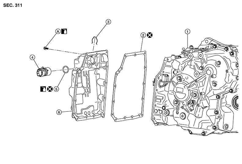
Exploded View
|
1. |
Transaxle assembly |
2. |
Control valve cover gasket |
3. |
Snap ring |
|
4. |
Terminal assembly |
5. |
O-ring |
6. |
Control valve cover |
|
A |
Refer to Removal and Installation. |
Removal and Installation
Removal and Installation
REMOVAL
Remove front under cover. Refer to Removal and Installation.
Remove drain plug (1) and drain
the CVT fluid. 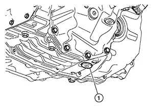
Remove drain plug O-ring (1). 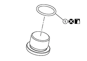
CAUTION:
Do not reuse O-ring.
Remove the air cleaner assembly and air cleaner bracket. Refer to Removal and Installation.
Disconnect the harness connector
(A) at top of CVT control valve cover. Refer to Removal and Installation
Procedure for CVT Unit Connector. 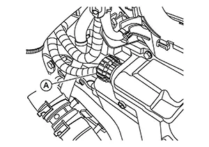
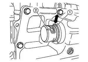
Pull the clip (1) from the terminal
assembly (2).
Partially remove the (LH) fender protector. Refer to Exploded View.
Remove the bolt and position the resonator aside. Refer to Exploded View.
Remove bolts and position the CVT oil warmer aside. Remove the O-rings. Refer to Removal and Installation.
CAUTION:
Do not reuse O-rings.
Remove control valve cover bolts
( ).
). 
Carefully lower the control valve cover, pull the terminal assembly out, and remove the control valve cover.
Remove control valve cover gasket.
CAUTION:
Do not reuse control valve cover gasket.
Remove the O-ring from the terminal assembly.
CAUTION:
Do not reuse O-ring.
INSTALLATION
Note the following and installation is in the reverse order of removal.
CAUTION:
-
Do not reuse control valve cover gasket.
-
Do not reuse drain plug O-ring.
-
Do not reuse oil warmer O-rings.
-
Do not reuse terminal assembly O-ring.
-
Install the control valve cover to the transaxle case with the following procedure:
-
Completely wipe out any moisture, oil, and clean the control valve cover gasket surface and transaxle case.
-
Install the control valve cover gasket to the transaxle case.
-
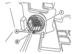
Install a new O-ring on the terminal assembly (1). Install the terminal assembly into the control valve cover in the correct orientation, with the tabs (A) over the boss (B) in the cover.
-
Install the clip (1) into the terminal assembly (2).
-
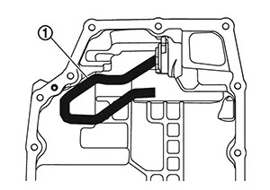
Position the control valve cover and route the harness (1) as shown.
-
Install the control valve cover onto the transaxle case, and then temporarily tighten the control valve cover bolts.
-
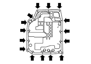
Tighten the control valve cover bolts to specification in sequence as shown.
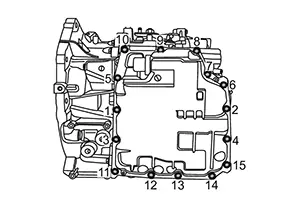
Control valve cover bolts
: 5.9 N·m (0.6 kg-m, 52 in-lb)
-
Install the CVT oil warmer. Refer to Exploded View.
-
Install the resonator. Refer to Exploded View.
-
Install the (LH) fender protector. Refer to Exploded View.
-
Connect the wire harness connector to terminal assembly.
-
Install the air cleaner bracket and air cleaner assembly. Refer to Removal and Installation.
-
Install the drain plug and tighten to specification. Refer to Exploded View.
-
Perform CVT fluid refilling. Refer to Refilling.
Inspection
Inspection
INSPECTION AFTER REMOVAL
Check points where wear is found in all cases.
If a large amount of worn material is found, clutch plate may be worn.
If iron powder is found, bearings, gears, or clutch plates may be worn.
If aluminum powder is found, bushing may be worn, or chips or burrs of aluminum casting parts may enter.
Check control valve cover for foreign material.
INSPECTION AFTER INSTALLATION
Start the engine and check visually that there are no leaks.
Other materials:
Sonar System. Preparation. Preparation
Preparation
Special Service Tools
Special Service Tools
The actual shape of the tools may differ from
those illustrated here.
Tool number
(TechMate No.)
Tool name
D ...
Component Parts
Exterior Lighting System
Component Parts Location
Component Parts
Location
A.
View of instrument panel
B.
M/T transmi ...
C1714-7b Low Tire Pressure Rr
Dtc Description
DTC Description
Note:
The Signal Tech II Tool [– (NI-50190)] can be used
to perform the following functions: Refer to the Signal Tech II User
Guide for additional information.
Activate and display TPMS sensor IDs
Display tire pressure rep ...