Nissan Sentra Service Manual: Control cable
Exploded View
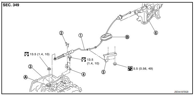
- Control cable
- Lock plate
- Transaxle assembly
- Bracket A
- Bracket B
- CVT shift selector assembly
- Manual lever
- Grommet
Removal and Installation
INSTALLATION
CAUTION:
Always apply the parking brake before performing removal and installation.
- Apply the parking brake.
CAUTION:
Make sure the vehicle cannot move with the parking brake applied.
- Remove the center console assembly. Refer to IP-17, "Removal and Installation".
- Move the shift selector to “P” position
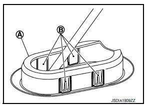
- Remove the control cable from the shift selector assembly with the following procedure.
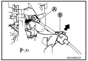
- Disconnect the tip (A) of control cable from the shift selector assembly.
- Remove socket (B) from shift selector assembly.
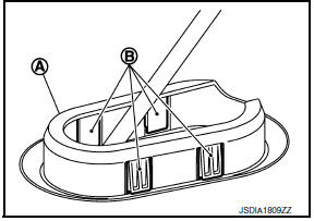
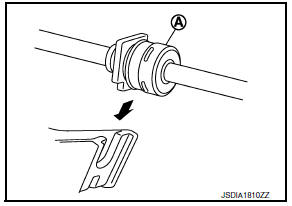
- Disengage the pawls (B) of the grommet (A), and pull downwards to remove.
- Remove the battery. Refer to PG-50, "Removal and Installation (Battery)".
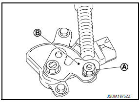
- Remove the control cable installation nut (A) from the manual lever (B).
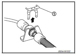
- Remove the lock plate (1).
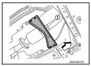
- Remove the tunnel stay (1).
 : Front
- Remove the exhaust front tube and sub muffler from the exhaust system. Refer to EX-5, "Removal and Installation".
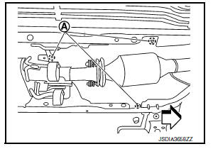
- Remove the heat plate fixtures (A).
 : Front
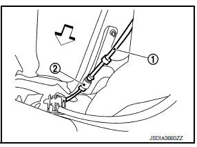
- Remove the control cable (1) from the bracket (2).
 : Front
- Remove the control cable from the vehicle.
INSTALLATION
Installation is in the reverse order of removal.
- From below the vehicle, press the grommet (A) into place until the pawls (B) make a click sound.
CAUTION:
- Place the grommet on the floor, then fasten it in place from below the vehicle.
- Check that pulling down on the grommet does not disconnect it.
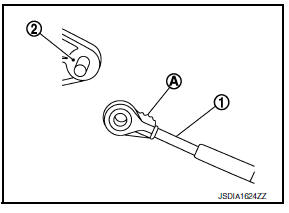
- Pay attention to the following when connecting the control cable to the shift selector.
- When connecting the control cable (1) to the shift selector assembly (2), face the grooved surface of the rib (A) up and insert the control cable until it stops.
- Install the socket (A) onto the shift selector.
CAUTION:
- Place the socket onto the shift selector, then fasten it in place from above.
- Check that the pulling on the socket does not disconnect it.
Inspection and Adjustment
INSPECTION AND ADJUSTMENT
Check the CVT position. If a malfunction is found, adjust the CVT position. Refer to TM-150, "Inspection" (Inspection) or TM-150, "Adjustment" (Adjustment).
 CVT Shift selector
Exploded View
Shift selector knob
Lock pin
Knob cover
Position indication panel
Detent switch
Shift lock unit
Park position switch
Shift selector assembly
Shift selector harne ...
 Key interlock cable
Exploded View
Shift selector assembly
Clip
Key interlock cable
Clip
Key cylinder
Removal and Installation
REMOVAL
CAUTION:
Always apply the parking brake before performing remov ...
Other materials:
Engine assembly M/T
M/T : Exploded View
Washer
Upper torque rod (RH)
Engine mounting insulator (RH)
Rear torque rod bracket
Rear torque rod
Engine mounting bracket (LH)
Engine mounting frame support (LH)
Engine mounting insulator (LH)
CAUTION:
Check that the stud bolt (*2) is tight at the spe ...
Power outlet
Center Console
Console Box (if so equipped)
The power outlets are for powering electrical
accessories such as cellular telephones. They
are rated at 12 volt, 120W (10A) maximum.
The power outlets are powered only when the
ignition switch is in the ACC or ON position.
CAUTION
The ...
Anti-pinch system does not operate normally (driver side)
Diagnosis Procedure
1.CHECK POWER WINDOW AUTO OPERATION
Check AUTO operation when anti-pinch function does not operate.
Refer to PWC-67, "Diagnosis Procedure".
Is the inspection result normal?
YES >> INSPECTION END
NO >> GO TO 2.
2.REPLACE POWER WINDOW MAIN SWITCH
...
