Nissan Sentra Service Manual: CVT Shift selector
Exploded View
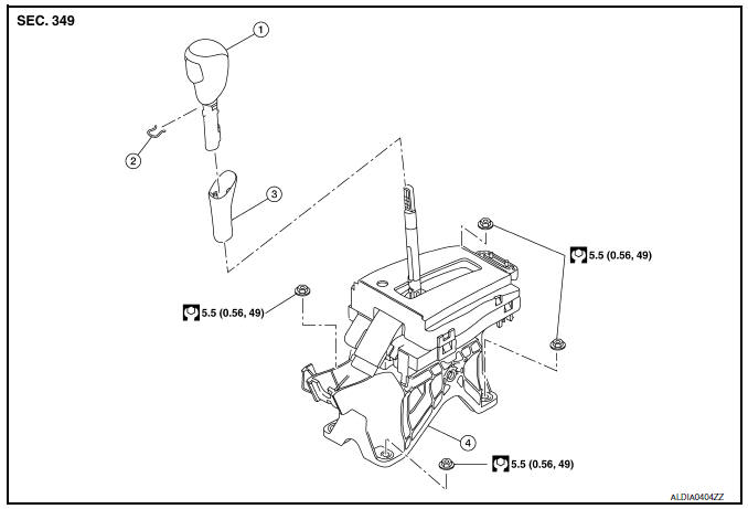
- Shift selector knob
- Lock pin
- Knob cover
- Position indication panel
- Detent switch
- Shift lock unit
- Park position switch
- Shift selector assembly
- Shift selector harness assembly
- Position bulb
- Key interlock rod
- With push-button ignition switch system
- Without push-button ignition switch system
Removal and Installation
REMOVAL
- Turn ignition switch OFF.
- Move the shift selector to “N” position
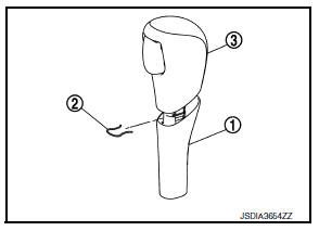
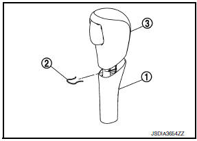
- Remove shift selector knob with the following procedure.
- Slide the knob cover (1) down.
CAUTION:
Do not damage the knob cover.
- Pull out the lock pin (2).
- Pull the shift selector knob (3) and knob cover upwards to remove them.
- Remove the center console. Refer to IP-17, "Removal and Installation".
- Remove rear floor duct (LH/RH). Refer to VTL-8, "Exploded View".
- Move the shift selector to “P” position.
- Remove the key interlock cable from the shift selector assembly. Refer
to TM-260, "Removal and Installation".
(Without push-button ignition switch)
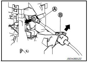
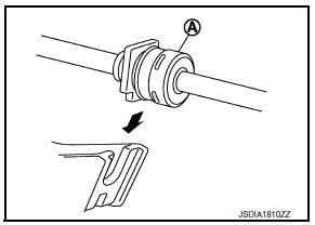
- Remove the control cable from the shift selector assembly with the following procedure.
- Disconnect the tip (A) of control cable from the shift selector assembly.
- Remove socket (B) from shift selector assembly.
- Remove harness clips from the shift selector with a clip remover.
- Remove shift selector nuts.
- Remove the shift selector assembly from the vehicle.
INSTALLATION
Installation is in the reverse order of removal.
NOTE:
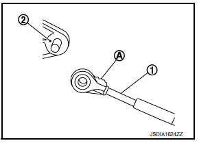
Pay attention to the following when connecting the control cable to the shift selector assembly.
- When connecting the control cable (1) to the shift selector assembly (2), face the grooved surface of the rib (A) up and insert the control cable until it stops.
- Install the socket (A) onto the shift selector assembly.
CAUTION:
- Place the socket onto the shift selector assembly, then fasten it in place from above.
- Check that the pulling on the socket does not disconnect it.
- Follow the procedure below and place the shift selector knob onto the shift selector.
- Install the lock pin (2) onto the shift selector knob (3).
- Move the shift selector to “N” position.
- Insert the shift selector knob into the shift selector until a slight touch is felt.
- Press and hold the shift selector knob button and insert shift selector knob onto shift selector until it clicks.
CAUTION:
Do not strike the shift selector knob to press it into place.
- After installing shift selector knob, pull the knob to check that it does not become disconnected.
Inspection
INSPECTION
Check the CVT position. If a malfunction is found, adjust the CVT position. Refer to TM-150, "Inspection".

 Control cable
Exploded View
Control cable
Lock plate
Transaxle assembly
Bracket A
Bracket B
CVT shift selector assembly
Manual lever
Grommet
Removal and Installation
INSTALLATION
CA ...
Other materials:
P1554 Battery current sensor
DTC Logic
DTC DETECTION LOGIC
DTC No.
CONSULT screen terms
(Trouble diagnosis content)
DTC detecting condition
Possible cause
P1554
BAT CURRENT SENSOR
(Battery current sensor)
The output voltage of the battery current
sensor is lower than the specified value ...
P1078 EVT Control position sensor
DTC Logic
DTC DETECTION LOGIC
DTC No.
CONSULT screen terms
(Trouble diagnosis content)
DTC detecting condition
Possible cause
P1078
EXH TIM SEN/CIRC-B1
(Exhaust valve timing control
position sensor circuit
bank 1)
An excessively high or low voltage from
...
Environmental factors influence the rate of corrosion
Moisture
Accumulation of sand, dirt and water on the vehicle
body underside can accelerate corrosion.
Wet floor coverings will not dry completely inside
the vehicle and should be removed for drying to
avoid floor panel corrosion.
Relative humidity
Corrosion will be accelerated in areas of h ...
