Nissan Sentra Service Manual: P1554 Battery current sensor
DTC Logic
DTC DETECTION LOGIC
| DTC No. | CONSULT screen terms (Trouble diagnosis content) | DTC detecting condition | Possible cause |
| P1554 | BAT CURRENT SENSOR (Battery current sensor) | The output voltage of the battery current sensor is lower than the specified value while the battery voltage is high enough. |
|
DTC CONFIRMATION PROCEDURE
1.PERFORM COMPONENT FUNCTION CHECK
Perform component function check. Refer to EC-383, "Component Function Check".
NOTE:
Use component function check to check the overall function of the battery current sensor circuit. During this check, a 1st trip DTC might not be confirmed.
Is the inspection result normal? YES >> INSPECTION END
NO >> Proceed to EC-384, "Diagnosis Procedure".
Component Function Check
1.PRECONDITIONING
TESTING CONDITION:
Before performing the following procedure, confirm that battery voltage is more than 12.8 V at idle.
Before performing the following procedure, confirm that all load switches and A/C switch are turned OFF.
>> GO TO 2.
2.PERFORM COMPONENT FUNCTION CHECK
 With CONSULT
- Start engine and let it idle.
- Select “BAT CUR SEN” in “DATA MONITOR” mode of “ENGINE” using CONSULT.
- Check “BAT CUR SEN” indication for 10 seconds.
“BAT CUR SEN” : above 2,300 mv at least once
 Without
CONSULT
- Start engine and let it idle.
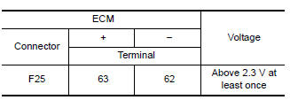
- Check the voltage between ECM harness connectors.
Is the inspection result normal? YES >> INSPECTION END
NO >> Proceed to EC-384, "Diagnosis Procedure".
Diagnosis Procedure
1.CHECK BATTERY CURRENT SENSOR POWER SUPPLY
- Turn ignition switch OFF.
- Disconnect battery current sensor harness connector
- Turn ignition switch ON.
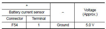
- Check the voltage between battery current sensor harness connector and ground.
Is the inspection result normal? YES >> GO TO 3.
NO >> GO TO 2.
2.CHECK SENSOR POWER SUPPLY 2 CIRCUIT
Check sensor power supply 2 circuit. Refer to EC-444, "Diagnosis Procedure".
Is the inspection result normal? YES >> Perform the trouble diagnosis for power supply circuit.
NO >> Repair or replace error-detected parts.
3.CHECK BATTERY CURRENT SENSOR GROUND CIRCUIT
- Turn ignition switch OFF.
- Disconnect ECM harness connector
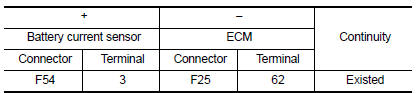
- Check the continuity between battery current sensor harness connector and ECM harness connector.
- Also check harness for short to power.
Is the inspection result normal? YES >> GO TO 4.
NO >> Repair or replace error-detected parts.
4.CHECK BATTERY CURRENT SENSOR INPUT SIGNAL CIRCUIT
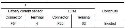
- Check the continuity between battery current sensor harness connector and ECM harness connector.
- Also check harness for short to ground and to power.
Is the inspection result normal? YES >> GO TO 5.
NO >> Repair or replace error-detected parts
5.CHECK BATTERY CURRENT SENSOR
Check the battery current sensor. Refer to EC-385, "Component Inspection (Battery Current Sensor)".
Is the inspection result normal? YES >> Check intermittent incident. Refer to GI-39, "Intermittent Incident".
NO >> Replace battery current sensor. Refer to PG-53, "Removal and Installation".
Component Inspection (Battery Current Sensor)
1.CHECK BATTERY CURRENT SENSOR
- Turn ignition switch OFF.
- Reconnect harness connectors disconnected.
- Disconnect battery negative cable.
- Install jumper cable between battery negative terminal and body ground.
- Turn ignition switch ON.
- Check the voltage between ECM harness connector terminals.
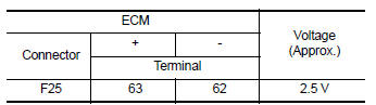
Before measuring the terminal voltage, confirm that the battery is fully charged. Refer to PG-4, "How to Handle Battery".
Is the inspection result normal?
YES >> INSPECTION END
NO >> Replace battery current sensor. Refer to PG-53, "Removal and Installation".
 P1553 Battery current sensor
DTC Logic
DTC DETECTION LOGIC
DTC No.
CONSULT screen terms
(Trouble diagnosis content)
DTC detecting condition
Possible cause
P1553
BAT CURRENT SENSOR
(Battery curr ...
 P1556, P1557 Battery temperature sensor
DTC Logic
DTC DETECTION LOGIC
NOTE:
If DTC P1556 or P1557 is displayed with DTC P0643, first perform the
trouble diagnosis for DTC P0643.
Refer to EC-353, "DTC Logic".
DTC No ...
Other materials:
Ecu diagnosis information
Audio unit
Reference value
TERMINAL LAYOUT
PHYSICAL VALUES
Bose speaker amp
Reference value
TERMINAL LAYOUT
PHYSICAL VALUES
BluetoothВ® control unit
Reference value
TERMINAL LAYOUT
PHYSICAL VALUES
...
FM/AM/SAT radio with compact disc (CD) player (Type A) (if so equipped)
For all operation precautions, see “Audio operation
precautions” in this section.
Audio main operation
VOL (volume) knob / PWR (power) button:
Place the ignition switch in the ACC or ON
position and press the VOL (volume) knob /PWR
(power) button while the system is off to call up
the mod ...
Audio system voice commands
To access the audio system voice commands:
Press the button.
Say “Audio”
Speak a command from the following available
commands:
Play (AM, FM, etc.)
Allows user to select radio band
Tune AM (number)
Allows user to tune directly to a desired AM
frequency
Tune FM (number)
...
