Nissan Sentra Service Manual: Key interlock cable
Exploded View
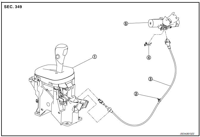
- Shift selector assembly
- Clip
- Key interlock cable
- Clip
- Key cylinder
Removal and Installation
REMOVAL
CAUTION:
Always apply the parking brake before performing removal and installation.
- Remove the steering column cover, and the instrument lower panel LH. Refer to IP-21, "Removal and Installation".
- Remove the center console assembly. Refer to IP-17, "Removal and Installation".
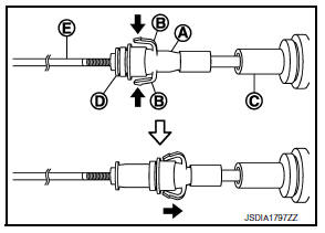
- Press the pawls (B) of the key interlock cable slider (A) while sliding it in the direction of the casing cap (C), and separate the adjusting holder (D) and slider.
(E) :Key interlock rod
- Remove the key interlock cable from the shift selector.
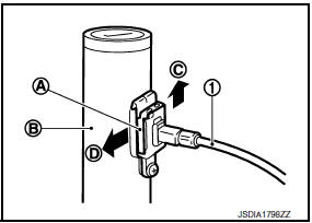
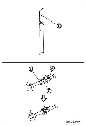
- Lift the clip (A) in the direction of the arrow (
![[C]) and remove](images/books/349/26/index285.gif)
[C]) and remove in the direction of the arrow (![[D]).](images/books/349/26/index286.gif)
[D]).
(1) : Key interlock cable
(B) : Key cylinder
- Remove the key interlock cable from the key cylinder.
- Disengage the clip and disconnect the key interlock cable from the vehicle.
INSTALLATION
- Move the shift selector to P position.
- Turn the ignition switch to ACC or ON position.
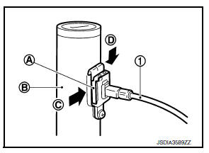
- Install the holder of key interlock cable to key cylinder.
- Install the clip (A) in the direction of the arrow (
![[C]) and push it](images/books/349/26/index288.gif)
[C]) and push it in the direction of the arrow ( [
[D]).
(1) : Key interlock cable
(B) : Key cylinder
- Turn the ignition switch to LOCK position.
- Install the adjusting holder (A) onto the key interlock rod (B), then install the casing cap (C) onto the shift selector cable bracket (D).
CAUTION:
- When installing the key interlock cable, never bend or twist the cable forcefully.
- After connecting the key interlock cable to the shift selector cable bracket, be sure to check that the casing cap is completely fastened to the cable bracket. If the casing cap is easily displaced, replace the key interlock cable.
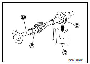
- While pressing the detent rod (B) down, slide the key interlock cable slider (A) toward the key interlock rod (D) side and install the adjusting holder (C) and key interlock rod.
CAUTION:
- Do not squeeze the pawls on the key interlock cable slider when holding the slider.
- Do not apply force in a perpendicular direction to the key interlock rod when sliding the slider.
- Install the center console assembly. Refer to IP-17, "Removal and Installation".
- Install the steering column cover, and the instrument lower panel LH. Refer to IP-21, "Removal and Installation".
Inspection
INSPECTION AFTER INSTALLATION
- Check the CVT position. If a malfunction is found, adjust the CVT position. Refer to TM-150, "Adjustment".
- The key can be removed only when the shift selector is in the “P” position. (With key interlock)
- It must not be possible to turn the ignition switch to LOCK when the
selector lever is not in the “P” position.
(With key interlock)
 Control cable
Exploded View
Control cable
Lock plate
Transaxle assembly
Bracket A
Bracket B
CVT shift selector assembly
Manual lever
Grommet
Removal and Installation
INSTALLATION
CA ...
 TCM
TCM
Exploded View
Bracket
TCM
: Vehicle front
: NВ·m (kg-m, in-lb)
Removal and Installation
CAUTION:
When replacing TCM, note the “CVTF DETERIORATION DATE” value
displ ...
Other materials:
Power supply and ground circuit
BCM (BODY CONTROL SYSTEM) (WITH INTELLIGENT KEY SYSTEM)
BCM (BODY CONTROL SYSTEM) (WITH INTELLIGENT KEY SYSTEM) : Diagnosis Procedure
Regarding Wiring Diagram information, refer to BCS-51, "Wiring Diagram".
1.Check fuses and fusible link
Check that the following fuses and fusible link ...
A/c auto amp. Connection recognition signal circuit
Description
A/c auto amp. Transmits the a/c auto amp. Connection recognition signal to
the combination meter
Diagnosis procedure (with manual a/c)
Regarding wiring diagram information, refer to mwi-28, "wiring diagram".
1.Check a/c auto amp. Connection recognition signal
Turn ig ...
Slip indicator lamp
Component Function Check
1.CHECK SLIP INDICATOR LAMP FUNCTION
Check that slip indicator lamp in combination meter turns ON for
approximately 2 seconds after ignition switch
is turned ON.
Is the inspection result normal?
YES >> Inspection End.
NO >> Proceed to diagnosis proce ...
