Nissan Sentra Service Manual: Power supply and ground circuit
BCM (BODY CONTROL SYSTEM) (WITH INTELLIGENT KEY SYSTEM)
BCM (BODY CONTROL SYSTEM) (WITH INTELLIGENT KEY SYSTEM) : Diagnosis Procedure
Regarding Wiring Diagram information, refer to BCS-51, "Wiring Diagram".
1.Check fuses and fusible link
Check that the following fuses and fusible link are not blown.

Is the fuse blown? Yes >> replace the blown fuse or fusible link after repairing the affected circuit.
No >> go to 2.
2.Check power supply circuit
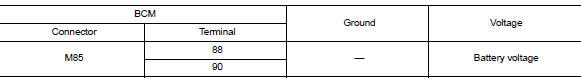
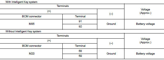
- Disconnect BCM connector M85.
- Check voltage between BCM connector M85 and ground.
Is the inspection result normal? Yes >> go to 3.
No >> repair harness or connector.
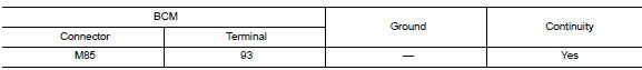
3.Check ground circuit
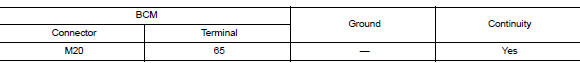
Check continuity between bcm connector m85 and ground.
Is the inspection result normal? Yes >> inspection end.
No >> repair harness or connector.
BCM (BODY CONTROL SYSTEM) (WITHOUT INTELLIGENT KEY SYSTEM)
BCM (BODY CONTROL SYSTEM) (WITHOUT INTELLIGENT KEY SYSTEM) : Diagnosis Procedure
Regarding wiring diagram information, refer to bcs-111, "wiring diagram".
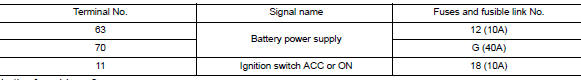
1.Check fuses and fusible link
Check that the following fuses and fusible link are not blown.
Is the fuse blown? Yes >> replace the blown fuse or fusible link after repairing the affected circuit.
No >> go to 2.
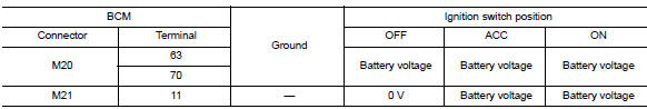
2.Check power supply circuit
- Turn ignition switch OFF.
- Disconnect BCM connectors.
- Check voltage between bcm connector and ground.
Is the inspection result normal? Yes >> go to 3.
No >> repair harness or connector.
3.Check ground circuit
Check continuity between bcm connector and ground.
Is the inspection result normal? Yes >> inspection end.
No >> repair harness or connector.
POWER WINDOW MAIN SWITCH
POWER WINDOW MAIN SWITCH : Description
- Bcm supplies power.
- It operates each power window motor via corresponding power window switch and makes window move up/ down when main power window and door lock/unlock switch is operated.
POWER WINDOW MAIN SWITCH : Component Function Check
Main power window and door lock/unlock switch
1. Check main power window and door lock/unlock switch function
Check power window motor operation with main power window and door lock/unlock switch.
Is the inspection result normal? YES >> Main power window and door lock/unlock switch power supply and ground circuit are OK.
NO >> Refer to PWC-33, "POWER WINDOW MAIN SWITCH : Diagnosis Procedure".
POWER WINDOW MAIN SWITCH : Diagnosis Procedure
Regarding wiring diagram information, refer to pwc-18, "wiring diagram".
Main power window and door lock/unlock switch power supply circuit check
1. Check power supply circuit
- Turn ignition switch ON.
- Check voltage between main power window and door lock/unlock switch connectors D5, D11 and ground.
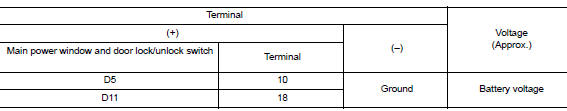
Is the inspection result normal? Yes >> go to 3.
No >> go to 2.
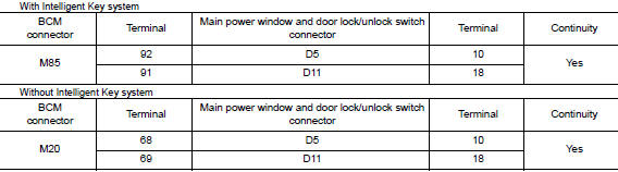
2. Check harness continuity
- Turn ignition switch off.
- Disconnect bcm, main power window and door lock/unlock switch, power window and door lock/unlock switch rh, rear power window switch lh and rear power window switch rh.
- Check continuity between bcm connector and main power window and door lock/unlock switch connectors.
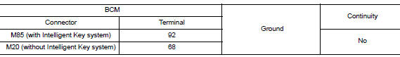
- Check continuity between bcm connector m85 or m20 and ground.
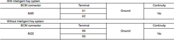
Is the inspection result normal? Yes >> go to 4.
No >> repair or replace the harness or connectors.
3. Check ground circuit
- Turn ignition switch off.
- Disconnect main power window and door lock/unlock switch.
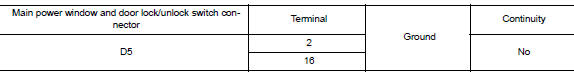
- Check continuity between main power window and door lock/unlock switch connector d11 and ground.

Is the inspection result normal? Yes >> check main power window and door lock/unlock switch output signal (rear power window switch lh) go to 5.
Yes >> check main power window and door lock/unlock switch output signal (rear power window switch rh) go to 6.
Yes >> check main power window and door lock/unlock switch output signal (front power window switch lh) go to 7.
Yes >> check main power window and door lock/unlock switch output signal (front power window switch rh) go to 8.
No >> repair or replace the harness or connectors.
4. Check bcm output signal
- Connect bcm.
- Turn ignition switch ON.
- Check voltage between BCM connector M85 or M20 and ground.
Is the inspection result normal? Yes >> check intermittent incident. Refer to gi-39, "intermittent incident".
No >> replace bcm. Refer to bcs-73, "removal and installation" (with intelligent key) or bcs-126, "removal and installation" (without intelligent key).
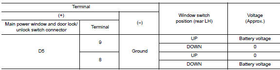
5. Check main power window and door lock/unlock switch output signal (rear power window switch lh)
- Connect main power window and door lock/unlock switch.
- Turn ignition switch on.
- Check voltage between main power window and door lock/unlock switch d5 and ground.
Is the inspection result normal? Yes >> check intermittent incident. Refer to gi-39, "intermittent incident".
No >> replace main power window and door lock/unlock switch. Refer to pwc-70, "removal and installation".
After that, refer to pwc-29, "work procedure".
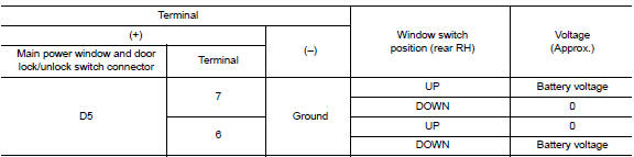
6. Check main power window and door lock/unlock switch output signal (rear power window switch rh)
- Connect main power window and door lock/unlock switch.
- Turn ignition switch ON.
- Check voltage between main power window and door lock/unlock switch d5 and ground.
Is the inspection result normal? Yes >> check intermittent incident. Refer to gi-39, "intermittent incident".
No >> replace main power window and door lock/unlock switch. Refer to pwc-70, "removal and installation".
After that, refer to pwc-29, "work procedure"
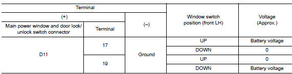
7. Check main power window and door lock/unlock switch output signal (front power window switch lh)
- Connect main power window and door lock/unlock switch.
- Turn ignition switch ON.
- Check voltage between main power window and door lock/unlock switch d11 and ground.
Is the inspection result normal? YES >> Check intermittent incident. Refer to GI-39, "Intermittent Incident".
NO >> Replace main power window and door lock/unlock switch. Refer to PWC-70, "Removal and Installation".
After that, refer to PWC-29, "Work Procedure".
8. Check main power window and door lock/unlock switch output signal (front power window switch rh)
- Connect main power window and door lock/unlock switch.
- Turn ignition switch ON.
- Check voltage between main power window and door lock/unlock switch D5 and ground.
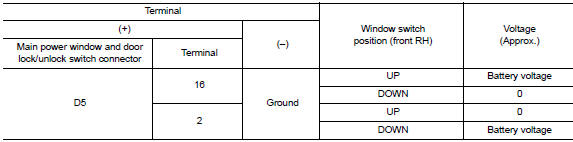
Is the inspection result normal? YES >> Check intermittent incident. Refer to GI-39, "Intermittent Incident".
NO >> Replace main power window and door lock/unlock switch. Refer to PWC-70, "Removal and Installation".
After that, refer to PWC-29, "Work Procedure".
POWER WINDOW MAIN SWITCH : Component Inspection
1. Check main power window and door lock/unlock switch
- Check main power window and door lock/unlock switch D5.
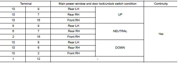
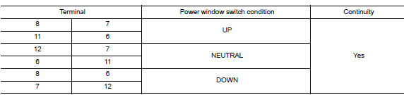
- Check continuity between main power window and door lock/unlock switch d5 (power window lock switch) (lock operation).
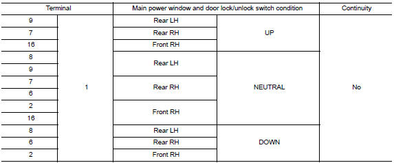
- Check continuity between main power window and door lock/unlock switch d5 (power window lock switch) (unlock operation).
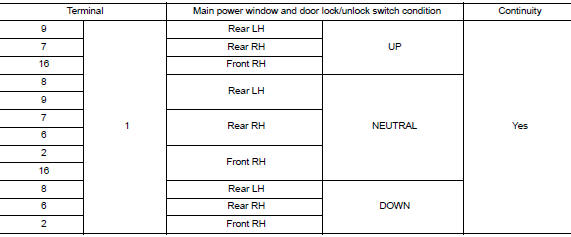
Is the inspection result normal? YES >> Main power window and door lock/unlock switch is OK.
NO >> Replace main power window and door lock/unlock switch. Refer to PWC-70, "Removal and Installation".
After that, refer to PWC-29, "Work Procedure".
POWER WINDOW MAIN SWITCH : Special Repair Requirement
1. Perform initialization procedure
Perform initialization procedure.
Refer to pwc-29, "work procedure".
Is the inspection result normal? Yes >> go to 2.
No >> check intermittent incident. Refer to gi-39, "intermittent incident".
2. Check anti-pinch operation
Check anti-pinch operation.
Refer to pwc-30, "work procedure".
Is the inspection result normal? Yes >> inspection end.
No >> refer to pwc-32, "power window main switch : component function check".
FRONT POWER WINDOW SWITCH
FRONT POWER WINDOW SWITCH : Description
- Bcm supplies power.
- Front power window motor RH will be operated if power window and door lock/unlock switch RH is operated
FRONT POWER WINDOW SWITCH : Component Function Check
Power window and door lock/unlock switch rh
1. Check power window motor function
Check front power window motor operation with power window and door lock/unlock switch rh.
Is the inspection result normal? Yes >> power window and door lock/unlock switch rh power supply and ground circuit are ok.
No >> refer to pwc-37, "front power window switch : diagnosis procedure".
FRONT POWER WINDOW SWITCH : Diagnosis Procedure
Regarding Wiring Diagram information, refer to PWC-18, "Wiring Diagram".
Power window and door lock/unlock switch rh power supply circuit check
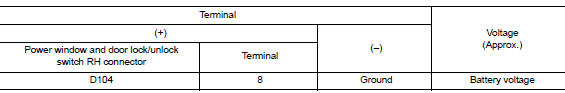
1. Check power supply circuit (power window and door lock/unlock switch rh)
- Turn ignition switch ON.
- Check voltage between power window and door lock/unlock switch rh connector d104 and ground.
Is the inspection result normal? YES >> GO TO 3.
NO >> GO TO 2.
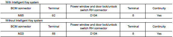
2. Check harness continuity
- Turn ignition switch OFF.
- Disconnect bcm, power window and door lock/unlock switch rh, rear power window switch lh and rear power window switch rh.
- Check continuity between bcm connector m85 or m20 and power window and door lock/unlock switch rh connector d104.
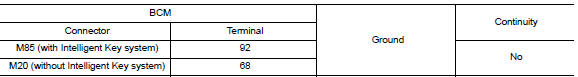
- Check continuity between bcm connector m85 or m20 and ground.
Is the inspection result normal? Yes >> go to 4.
No >> repair or replace the harness or connectors.
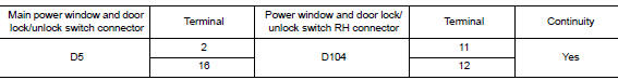
3. Check harness continuity (power window and door lock/unlock switch rh)
- Turn ignition switch off.
- Disconnect main power window and door lock/unlock switch and power window and door lock/unlock switch rh.
- Check continuity between main power window and door lock/unlock switch connector D5 and power window and door lock/unlock switch RH connector D104.
- Check continuity between main power window and door lock/unlock switch connector d5 and ground.
Is the inspection result normal? Yes >> go to 5
No >> repair or replace the harness or connectors.
4. Check bcm output signal
- Connect BCM.
- Turn ignition switch on.
- Check voltage between bcm connector m85 or m20 and ground.
Is the inspection result normal? YES >> Check intermittent incident. Refer to GI-39, "Intermittent Incident".
NO >> Replace BCM. Refer to BCS-73, "Removal and Installation" (with Intelligent Key) or BCS-126, "Removal and Installation" (without Intelligent Key).
5. Check power window and door lock/unlock switch rh
Check power window and door lock/unlock switch rh.
Refer to pwc-39, "front power window switch : component inspection".
Is the inspection result normal? Yes >> check intermittent incident. Refer to gi-39, "intermittent incident".
No >> replace power window and door lock/unlock switch rh. Refer to pwc-71, "removal and installation".
FRONT POWER WINDOW SWITCH : Component Inspection
Component inspection
1. Check power window and door lock/unlock switch rh
Check power window and door lock/unlock switch rh d104.
Is the inspection result normal? Yes >> power window and door lock/unlock switch rh is ok.
No >> replace power window and door lock/unlock switch rh. Refer to pwc-71, "removal and installation".
REAR POWER WINDOW SWITCH
REAR POWER WINDOW SWITCH : Description
- BCM supplies power.
- Rear power window motor will be operated if rear power window switch is operated. Rear power window switch.
REAR POWER WINDOW SWITCH : Component Function Check
Rear power window switch
1. Check rear power window motor function
Check rear power window motor operation with rear power window switch.
Is the inspection result normal? Yes >> rear power window switch power supply and ground circuit are ok.
No >> refer to pwc-40, "rear power window switch : diagnosis procedure".
REAR POWER WINDOW SWITCH : Diagnosis Procedure
Regarding wiring diagram information, refer to pwc-18, "wiring diagram".
Rear power window switch power supply circuit check
1. Check power supply circuit
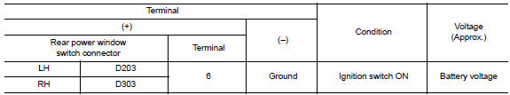
- Turn ignition switch ON.
- Check voltage between rear power window switch connector d203 or d303 and ground.
Is the inspection result normal? Yes >> go to 2 (rear power window switch lh).
Yes >> go to 3 (rear power window switch rh).
No >> go to 4.
Is the inspection result normal? Yes >> go to 2 (rear power window switch lh).
Yes >> go to 3 (rear power window switch rh).
No >> go to 4.
2. Check harness continuity (rear power window switch lh)
- Turn ignition switch off.
- Disconnect main power window and door lock/unlock switch and rear power window switch LH.
- Check continuity between main power window and door lock/unlock switch connector D5 and rear power window switch LH connector D203.
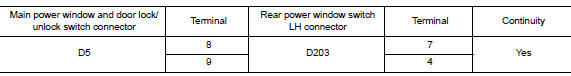
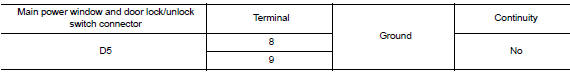
- Check continuity between main power window and door lock/unlock switch connector d5 and ground.
Is the inspection result normal? Yes >> go to 5.
No >> repair or replace the harness or connectors.
3. Check harness continuity (rear power window switch rh)
- Turn ignition switch off.
- Disconnect main power window and door lock/unlock switch and rear power window switch rh.
- Check continuity between main power window and door lock/unlock switch connector d5 and rear power window switch rh connector d303.
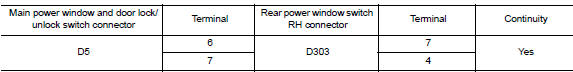
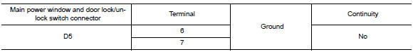
- Check continuity between main power window and door lock/unlock switch connector D5 and ground.
Is the inspection result normal? YES >> GO TO 5.
NO >> Repair or replace the harness or connectors.
4. Check harness continuity
- Disconnect bcm, power window and door lock/unlock switch rh, rear power window switch lh and rear power window switch rh.
- Check continuity between BCM connector and rear power window switch connector.
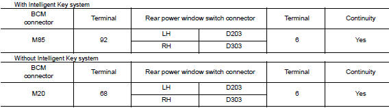
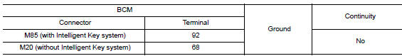
- Check continuity between BCM connector M85 or M20 and ground.
Is the inspection result normal? YES >> Replace BCM. Refer to BCS-73, "Removal and Installation" (with Intelligent Key) or BCS-126, "Removal and Installation" (without Intelligent Key).
NO >> Repair or replace harness or connectors.V
5. Check rear power window switch
Check rear power window switch.
Refer to pwc-42, "rear power window switch : component inspection".
Is the inspection result normal? Yes >> check intermittent incident. Refer to gi-39, "intermittent incident".
No >> replace rear power window switch. Refer to pwc-72, "removal and installation".
REAR POWER WINDOW SWITCH : Component Inspection
Component inspection
1. Check rear power window switch
Check rear power window switch.
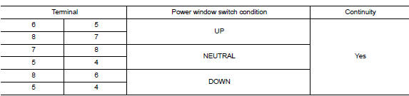
Is the inspection result normal? YES >> Rear power window switch is OK.
NO >> Replace rear power window switch. Refer to PWC-72, "Removal and Installation".

 Power window motor
DRIVER SIDE
DRIVER SIDE : Description
Door glass moves up/down by receiving the signal from main power window and
door lock/unlock switch
DRIVER SIDE : Component Function Check
1. Check front po ...
Other materials:
Dtc/circuit diagnosis
U1000 can comm circuit
DTC Logic
Dtc detection logic
Consult display
Dtc detection condition
Possible cause
Can comm circuit
[u1000]
Av control unit is not transmitting or receiving
can communication signal for 2 seconds or
more.
CAN communication system.
...
NISSAN vehicle immobilizer system
The NISSAN Vehicle Immobilizer system will not
allow the engine to start without the use of the
registered key.
If the engine fails to start using a registered key
(for example, when interference is caused by
another registered key, an automated toll road
device or automatic payment device o ...
System
STARTING SYSTEM (WITH INTELLIGENT KEY)
Component Parts Location
Starter motor
Transmission range switch (CVT Models)
IPDM E/R (view with air inlet duct
removed)
Clutch interlock switch (M/T Models)
ECM
Component Description
Component part
Description
Starter ...
