Nissan Sentra B18 (2020-2025) Service Manual: Components
-
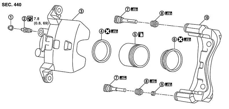
THE LARGE ILLUSTRATIONS are exploded views (see the following) and contain tightening torques, lubrication points, section number of the PARTS CATALOG (e.g. SEC. 440) and other information necessary to perform repairs.
The illustrations should be used in reference to service matters only. When ordering parts, refer to the appropriate PARTS CATALOG.
Always check with the PARTS DEPARTMENT for the latest parts information.
Components shown in an illustration may be identified by a circled number. When this style of illustration is used, the text description of the components will follow the illustration.
|
1. |
Cap |
2. |
Bleeder valve |
3. |
Cylinder body |
|
4. |
Piston seal |
5. |
Piston |
6. |
Piston boot |
|
7. |
Sliding pin |
8. |
Sliding pin boot |
9. |
Bushing |
|
10. |
Torque member |
||||
|
|
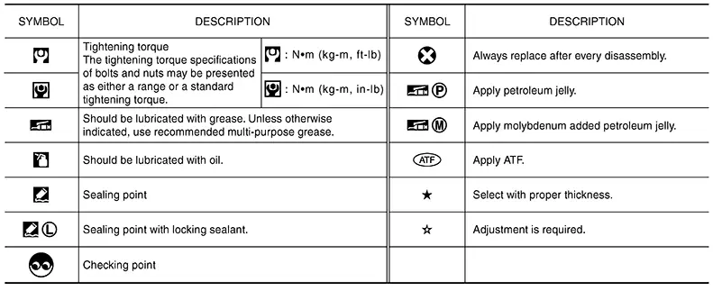
: Apply rubber grease. |
||||
|
|
: Apply brake fluid. |
||||
|
|
: N·m (kg-m, in-lb) |
||||
|
|
: Always replace after every disassembly |
||||


SYMBOLS
 Relation Between Illustrations and Descriptions
Relation between Illustrations and Descriptions
The following sample explains the relationship
between the part description in an illustration, the part name in
the text and the service proc ...

Other materials:
Removal and Installation - Boot
Removal and Installation - Boot
REMOVAL
Remove
outer socket. Refer to Removal and Installation - Outer
socket.
Remove
inner socket lock nut.
Remove
small boot clamp and large boot clamp.
CAUTION:
Do not reuse boot clamps.
Remove
boot.
CAUTIO ...
Moonroof switch
Removal and installation
REMOVAL
Remove the map lamp. Refer to INL-52, "Removal and Installation".
Release the pawls and remove the moonroof switch finisher (1).
: Pawl
Release the pawls and remove the moonroof switch (2).
: Pawl
INSTALLATION
Installation is in the ...
Confirmation Procedure
Confirmation Procedure
PRECONDITIONING
If “Confirmation Procedure” has been
previously conducted, always place the ignition switch OFF and wait
at least 10 seconds before conducting the next test.
>&g ...
