Nissan Sentra B18 (2020-2025) Service Manual: Component Parts
Eco Mode System
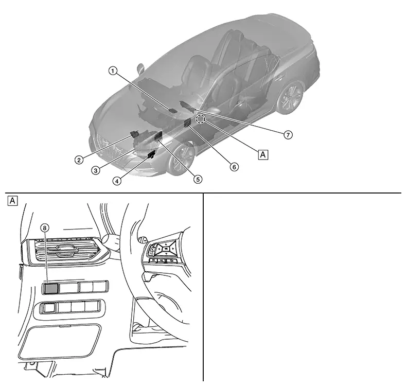
Component Parts Location
|
A. |
Instrument lower panel LH |
COMPONENT DESCRIPTION
|
No. |
Component |
Function |
|---|---|---|
|
1. |
A/C auto amp. (Auto A/C) |
The A/C auto amp. or A/C amp. receives the ECO mode signal from the BCM via CAN communication. Refer to Component Parts Location (Auto A/C), Component Parts Location (Manual A/C) for detailed component location. |
|
A/C amp. (Manual A/C) |
||
|
2. |
Electric throttle control actuator |
Refer to Component Description for detailed component location. |
|
3. |
Trans axle assembly |
Refer to Component Parts Location for detailed component location. |
|
4. |
TCM (Transmission Control Module) |
The TCM receives the ECO mode signal from the BCM via CAN communication. Refer to Component Parts Location for detailed component location. |
|
5. |
ECM (Engine Control Module) |
The ECM receives the ECO mode signal from the BCM via CAN communication. Refer to Component Parts Location for detailed component location. |
|
6. |
BCM (Body Control Module) |
Refer to System Description. |
|
7. |
Combination meter |
The combination meter receives the ECO mode indicator signal via CAN communication from the BCM. Refer to Component Parts Location (Type A) or Component Parts Location (Type B) for detailed component location. |
|
8. |
ECO mode switch |
Refer to ECO Mode Switch. |
Eco Mode Switch
-
The ECO mode switch is installed to the instrument lower finisher.

-
When the ECO mode indicator lamp on the combination meter is OFF and the ECO mode switch is pressed, the ECO mode is active and the ECO mode indicator lamp is ON.
-
When the ECO mode indicator lamp on the combination meter is ON and the ECO mode switch is pressed, the ECO mode is cancelled and the ECO mode indicator lamp is OFF.
Eco Mode Indicator Lamp
DESIGN/PURPOSE
The ECO mode indicator lamp inform the driver that the vehicle is in ECO mode.

SIGNAL PATH
-
Combination meter receives ECO mode switch signal (ON/OFF) from BCM via CAN communication.
Based on the signal, BCM transmits ECO mode signal to ECM via CAN communication.
-
ECM transmits ECO mode indicator signal to combination meter via CAN communication. Based on the signal, combination meter illuminates ECO mode indicator lamp.
LIGHTING CONDITION
When all of the following conditions are satisfied.
-
Ignition switch: ON
-
The ECO mode switch is pressed when the ECO mode indicator lamp is OFF
SHUTOFF CONDITION
When any of the condition listed below is satisfied.
-
Ignition switch: Other than ON
-
The ECO mode switch is pressed when the ECO mode indicator lamp is ON.

 System
Eco Mode Control
System Description
System Description
SYSTEM DIAGRAM
INPUT/OUTPUT SIGNAL CHART
Signal name
...
Other materials:
Shipping Mode Control System
System Description
System Description
SYSTEM DIAGRAM
OUTLINE
The BCM has the shipping mode control system
function that reduces the drain on the battery during extended
storage.
Signal transmission function list
...
Seat Belt Warning Chime
Seat Belt Warning Chime
Seat Belt Warning
Chime
SYSTEM DIAGRAM
DESCRIPTION
Seat belt warning chime warns the driver that driver
seat belt, passenger seat belt, or rear seat belts are not fastened.
WARNING OPERATION CONDITIONS
Front Seat Belts
Combination meter operates seat ...
Precautions
Precaution for Supplemental Restraint System (srs) "air Bag" and "seat Belt Pre-Tensioner"
Precaution for Supplemental Restraint System (SRS) "AIR BAG" and "SEAT BELT PRE-TENSIONER"
The Supplemental Restraint System such as
“AIR BAG” and “SEAT BELT PRE-TENSIONER”,
used along wit ...
