Nissan Sentra B18 (2020-2025) Service Manual: System Description
Component Parts
Eco Mode System
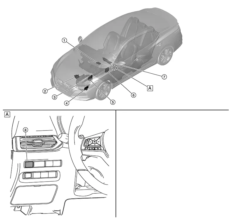
Component Parts Location
Component Parts Location
|
A. |
Instrument lower panel LH |
COMPONENT DESCRIPTION
|
No. |
Component |
Function |
|---|---|---|
|
1. |
A/C auto amp. (Auto A/C) |
The A/C auto amp. or A/C amp. receives the ECO mode signal from the BCM via CAN communication. Refer to Component Parts Location (Auto A/C), Component Parts Location (Manual A/C) for detailed component location. |
|
A/C amp. (Manual A/C) |
||
|
2. |
Electric throttle control actuator |
Refer to Component Description for detailed component location. |
|
3. |
Trans axle assembly |
Refer to Component Parts Location for detailed component location. |
|
4. |
TCM (Transmission Control Module) |
The TCM receives the ECO mode signal from the BCM via CAN communication. Refer to Component Parts Location for detailed component location. |
|
5. |
ECM (Engine Control Module) |
The ECM receives the ECO mode signal from the BCM via CAN communication. Refer to Component Parts Location for detailed component location. |
|
6. |
BCM (Body Control Module) |
Refer to System Description. |
|
7. |
Combination meter |
The combination meter receives the ECO mode indicator signal via CAN communication from the BCM. Refer to Component Parts Location (Type A) or Component Parts Location (Type B) for detailed component location. |
|
8. |
ECO mode switch |
Refer to ECO Mode Switch. |
Eco Mode Switch
ECO Mode Switch
-
The ECO mode switch is installed to the instrument lower finisher.

-
When the ECO mode indicator lamp on the combination meter is OFF and the ECO mode switch is pressed, the ECO mode is active and the ECO mode indicator lamp is ON.
-
When the ECO mode indicator lamp on the combination meter is ON and the ECO mode switch is pressed, the ECO mode is cancelled and the ECO mode indicator lamp is OFF.
Eco Mode Indicator Lamp
ECO Mode Indicator Lamp
DESIGN/PURPOSE
The ECO mode indicator lamp inform the driver that the vehicle is in ECO mode.

SIGNAL PATH
-
Combination meter receives ECO mode switch signal (ON/OFF) from BCM via CAN communication.
Based on the signal, BCM transmits ECO mode signal to ECM via CAN communication.
-
ECM transmits ECO mode indicator signal to combination meter via CAN communication. Based on the signal, combination meter illuminates ECO mode indicator lamp.
LIGHTING CONDITION
When all of the following conditions are satisfied.
-
Ignition switch: ON
-
The ECO mode switch is pressed when the ECO mode indicator lamp is OFF
SHUTOFF CONDITION
When any of the condition listed below is satisfied.
-
Ignition switch: Other than ON
-
The ECO mode switch is pressed when the ECO mode indicator lamp is ON.
System
Eco Mode Control
System Description
System Description
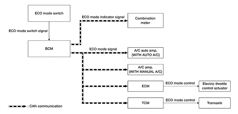
SYSTEM DIAGRAM
INPUT/OUTPUT SIGNAL CHART
|
Signal name |
Input |
Output |
Description |
|---|---|---|---|
|
ECO mode signal |
|
BCM |
Transmits ECO mode signal to ECM, TCM and A/C auto amp meter via CAN communication. |
|
ECO mode indicator signal |
Combination meter (CAN) |
BCM |
Transmits ECO mode indicator signal to combination meter via CAN communication. |
BCM CONTROL
-
BCM receives the ECO mode switch signal (ON/OFF) by hard wire. BCM transmits ECO mode signal to other control unit via CAN communication.
-
BCM transmits ECO mode indicator signal to combination meter via CAN communication. Combination meter illuminates ECO mode indicator according to the signal
-
For Air Conditioning Control details. Refer to System Description(Auto A/C) or System Description(Manual A/C).

-
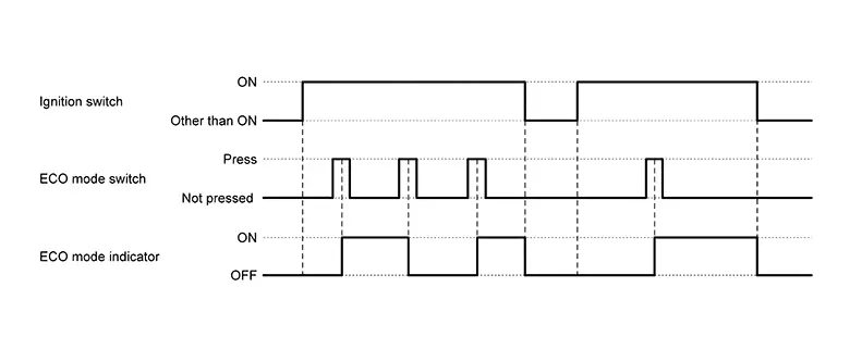
When the ignition switch is placed ON while the ECO mode indicator stays ON, the ECO mode indicator automatically turns ON at the next ignition switch ON.
-
The ECO mode system cannot be turned off while the accelerator pedal is depressed even if the ECO mode switch is pushed to OFF. (ECO mode indicator turns OFF.)
Release the accelerator pedal to turn off the ECO mode system.
ECM CONTROL
ECM receives the ECO mode signal from BCM via CAN communication and improves the fuel economy by controlling the throttle movement to less than usual.
TCM CONTROL
TCM receives the ECO mode signal from BCM via CAN communication and improves the fuel economy by controlling the driving characteristic (for decreasing needless acceleration and deceleration, reducing energy consumption, and fixing to ECO gear shift schedule), so that operation of fuel efficiency driving is assisted.
A/C AUTO AMP. CONTROL
For details of air conditioning control, Refer to System Description.
A/C AMP. CONTROL
For details of air conditioning control, Refer to System Description.
FAIL-SAFE
If a malfunction occurs in the system of CVT during ECO mode, the ECO mode is kept until ignition off, ECO mode is turned off automatically at the next ignition switch ON.
Warning/indicator/chime List
Warning / Indicator / Chime List
Warning / Indicator / Chime List
|
Name |
Function |
|---|---|
|
ECO mode indicator |
Refer to System Description. |
Eco Mode Indicator
System Description
System Description
DESIGN/PURPOSE
The ECO mode indicator informs the driver that the vehicle is in ECO mode.
OPERATION AT COMBINATION METER CAN COMMUNICATION CUT-OFF OR UNUSUAL SIGNAL
For actions on CAN communications blackout in the combination meter, Refer to Fail-Safe Combination meter (Type A) or Fail-Safe Combination meter (Type B).
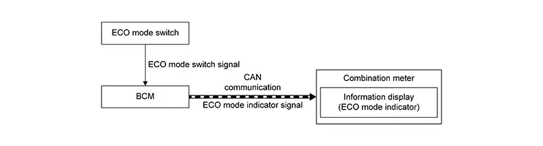
SYSTEM DIAGRAM
INPUT/OUTPUT SIGNAL CHART
|
Signal name |
Input |
Output |
Description |
|---|---|---|---|
|
ECO mode indicator signal |
Combination meter (CAN) |
BCM |
Transmits ECO mode indicator signal to combination meter via CAN communication. |
SIGNAL PATH
-
BCM receives the ECO mode switch signal (ON/OFF) by hard wire.
-
BCM transmits ECO mode indicator signal to combination meter via CAN communication. Combination meter illuminates ECO mode indicator according to the signal.
LIGHTING CONDITION
When all of the following conditions are satisfied.
-
Ignition switch: ON
-
The ECO mode switch is pressed when the ECO mode indicator is OFF
SHUTOFF CONDITION
When any of the condition listed below is satisfied.
-
Ignition switch: Other than ON
-
The ECO mode switch is pressed when the ECO mode indicator is ON.
TIMING CHART
Other materials:
C1076-55 Control Unit
Dtc Description
DTC Description
DTC DETECTION LOGIC
DTC No.
CONSULT screen item
(Trouble diagnosis
content)
DTC detection condition
...
B1040-22 Vehicle Speed
Dtc Description
DTC Description
DTC DETECTION LOGIC
Note:
This DTC may be detected when drive the Nissan Sentra vehicle
at vehicle speed of 186 MPH (300 km/h) or more.
DTC No.
CONSULT sc ...
Remote Keyless Entry Function
System Diagram
System Diagram
System Description
System Description
The Intelligent Key has the same functions as the
remote control entry system. Therefore, it can be used in the same
manner as the remote controller by operating the door lock/unlock
button.
OPERATION
Re ...