Nissan Sentra B18 (2020-2025) Service Manual: System
Eco Mode Control
System Description
SYSTEM DIAGRAM
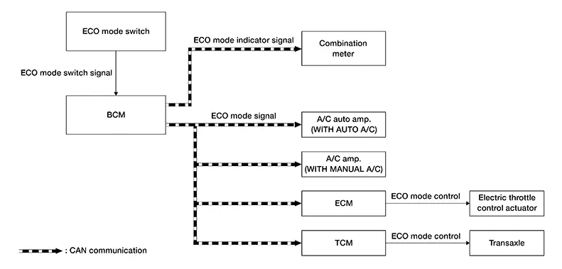
INPUT/OUTPUT SIGNAL CHART
|
Signal name |
Input |
Output |
Description |
|---|---|---|---|
|
ECO mode signal |
|
BCM |
Transmits ECO mode signal to ECM, TCM and A/C auto amp meter via CAN communication. |
|
ECO mode indicator signal |
Combination meter (CAN) |
BCM |
Transmits ECO mode indicator signal to combination meter via CAN communication. |
BCM CONTROL
-
BCM receives the ECO mode switch signal (ON/OFF) by hard wire. BCM transmits ECO mode signal to other control unit via CAN communication.
-
BCM transmits ECO mode indicator signal to combination meter via CAN communication. Combination meter illuminates ECO mode indicator according to the signal
-
For Air Conditioning Control details. Refer to System Description(Auto A/C) or System Description(Manual A/C).

-
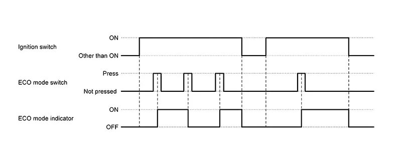
When the ignition switch is placed ON while the ECO mode indicator stays ON, the ECO mode indicator automatically turns ON at the next ignition switch ON.
-
The ECO mode system cannot be turned off while the accelerator pedal is depressed even if the ECO mode switch is pushed to OFF. (ECO mode indicator turns OFF.)
Release the accelerator pedal to turn off the ECO mode system.
ECM CONTROL
ECM receives the ECO mode signal from BCM via CAN communication and improves the fuel economy by controlling the throttle movement to less than usual.
TCM CONTROL
TCM receives the ECO mode signal from BCM via CAN communication and improves the fuel economy by controlling the driving characteristic (for decreasing needless acceleration and deceleration, reducing energy consumption, and fixing to ECO gear shift schedule), so that operation of fuel efficiency driving is assisted.
A/C AUTO AMP. CONTROL
For details of air conditioning control, Refer to System Description.
A/C AMP. CONTROL
For details of air conditioning control, Refer to System Description.
FAIL-SAFE
If a malfunction occurs in the system of CVT during ECO mode, the ECO mode is kept until ignition off, ECO mode is turned off automatically at the next ignition switch ON.
Warning/indicator/chime List
Warning / Indicator / Chime List
|
Name |
Function |
|---|---|
|
ECO mode indicator |
Refer to System Description. |
Eco Mode Indicator
System Description
DESIGN/PURPOSE
The ECO mode indicator informs the driver that the vehicle is in ECO mode.

OPERATION AT COMBINATION METER CAN COMMUNICATION CUT-OFF OR UNUSUAL SIGNAL
For actions on CAN communications blackout in the combination meter, Refer to Fail-Safe Combination meter (Type A) or Fail-Safe Combination meter (Type B).
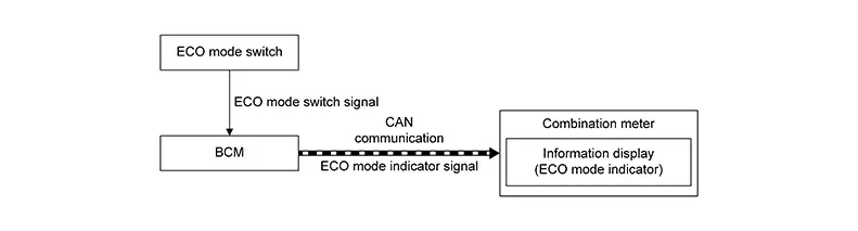
SYSTEM DIAGRAM
INPUT/OUTPUT SIGNAL CHART
|
Signal name |
Input |
Output |
Description |
|---|---|---|---|
|
ECO mode indicator signal |
Combination meter (CAN) |
BCM |
Transmits ECO mode indicator signal to combination meter via CAN communication. |
SIGNAL PATH
-
BCM receives the ECO mode switch signal (ON/OFF) by hard wire.
-
BCM transmits ECO mode indicator signal to combination meter via CAN communication. Combination meter illuminates ECO mode indicator according to the signal.
LIGHTING CONDITION
When all of the following conditions are satisfied.
-
Ignition switch: ON
-
The ECO mode switch is pressed when the ECO mode indicator is OFF
SHUTOFF CONDITION
When any of the condition listed below is satisfied.
-
Ignition switch: Other than ON
-
The ECO mode switch is pressed when the ECO mode indicator is ON.
TIMING CHART
 Component Parts
Eco Mode System
Component Parts Location
Component Parts
Location
A.
Instrument lower panel LH
...

Other materials:
Dtc Diagnosis Procedure
DTC Diagnosis
Procedure
CHECK FUSE
Ignition switch OFF.
Check that any of the following fuse is not blown
(open):
...
Additional service when replacing power window main switch
Description
When the power window main switch is replaced, the initialization is
necessary for normal operation of power
window system.
CAUTION:
The following specified operations can not be performed under the
non-initialized condition.
Auto-up operation
Anti-pinch function
Work Pr ...
Ecm, Bcm, Ipdm E/r
List of Ecu Reference
List of ECU
Reference
ECU
Reference
ECM
Values On The Diagnosis Tool
...
