Nissan Sentra Service Manual: Component parts
STARTING SYSTEM (WITH INTELLIGENT KEY)
Component Parts Location
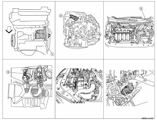
- Starter motor
- Transmission range switch (CVT Models)
- IPDM E/R (view with air inlet duct removed)
- Clutch interlock switch (M/T Models)
- ECM
- BCM (view under instrument panel, left side of vehicle)
Component Description
| Component part | Description |
| Starter motor | The starter motor plunger closes and the motor is supplied with battery power, which in turn cranks the engine, when the S terminal is supplied with electric power. |
| Transmission range switch (CVT Models) | Transmission range switch supplies power to the starter relay and starter control relay inside the IPDM E/R when the shift selector is placed in the P or N position. |
| IPDM E/R | CPU inside IPDM E/R operates the starter relay when the ignition switch is in the start position. |
| Clutch interlock switch (M/T Models) | Clutch interlock switch supplies power to the coil side of the starter when the clutch pedal is depressed to crank the engine. |
| ECM | ECM controls the starter control relay inside the IPDM E/R. |
| BCM | BCM controls the starter relay inside IPDM E/R. |

 System
STARTING SYSTEM (WITH INTELLIGENT KEY)
Component Parts Location
Starter motor
Transmission range switch (CVT Models)
IPDM E/R (view with air inlet duct
removed)
Clutch interlock switc ...
Other materials:
Map lamp
Removal and installation
Removal
Lower front edge of map lamp (1) down from the headlining by
releasing the metal clips, then slide forward to clear pawls at
rear.
: Metal clip
Pawl
Disconnect the harness connectors from the map lamp and remove.
Installation
Installation is in t ...
B0098 Front door satellite sensor RH
Description
DTC B0098 FRONT DOOR SATELLITE SENSOR RH
The front door satellite sensor RH is wired to the air bag diagnosis sensor
unit. The air bag diagnosis sensor
unit will monitor the front door satellite sensor RH for internal failures and
its circuits for communication errors.
PART LOCA ...
P0075 IVT control solenoid valve
DTC Logic
DTC DETECTION LOGIC
DTC No.
CONSULT screen terms
(Trouble diagnosis content)
DTC detecting condition
Possible cause
P0075
INT/V TIM V/CIR-B1
(Intake valve control solenoid
circuit bank 1)
An improper voltage is sent to the ECM
through intake val ...
