Nissan Sentra Service Manual: System
STARTING SYSTEM (WITH INTELLIGENT KEY)
Component Parts Location
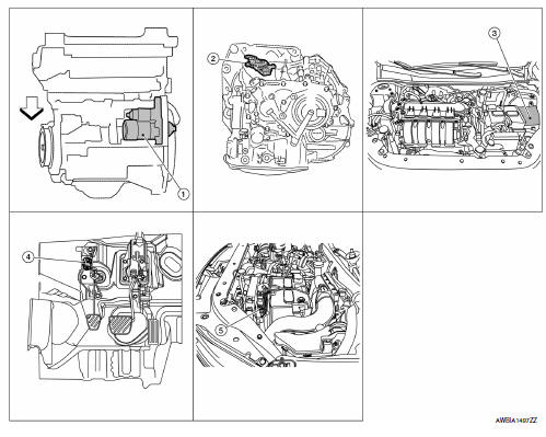
- Starter motor
- Transmission range switch (CVT Models)
- IPDM E/R (view with air inlet duct removed)
- Clutch interlock switch (M/T Models)
- ECM
Component Description
| Component part | Description |
| Starter motor | The starter motor plunger closes and the motor is supplied with battery power, which in turn cranks the engine, when the S terminal is supplied with electric power. |
| Transmission range switch | Supplies power to the starter relay and starter control relay (inside IPDM E/R) when the selector lever is shifted into the P or N position. |
| IPDM E/R | CPU inside IPDM E/R operates the starter relay when the ignition switch is in the start position. |
| Clutch interlock switch (M/T Models) | Clutch interlock switch supplies power to the coil side of the starter when the clutch pedal is depressed to crank the engine. |
| ECM | ECM controls the starter relay inside the IPDM E/R. |
STARTING SYSTEM (WITHOUT INTELLIGENT KEY)
System Diagram
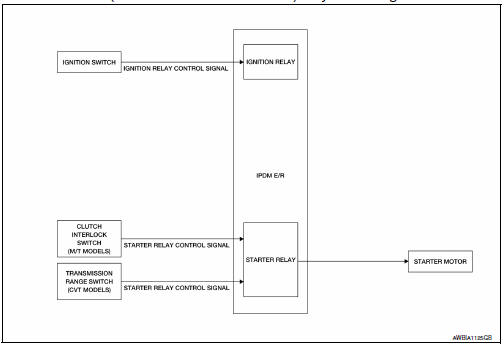
System Description
The starter motor plunger closes and provides a closed circuit between the battery and the starter motor. The starter motor is grounded to the cylinder block. With power and ground supplied, the starter motor operates.
STARTING SYSTEM (WITHOUT INTELLIGENT KEY)
STARTING SYSTEM (WITHOUT INTELLIGENT KEY) : System Diagram
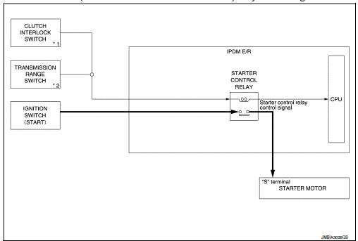
*1: M/T models
*2: CVT models
STARTING SYSTEM (WITHOUT INTELLIGENT KEY) : System Description
CVT MODELS
- When the selector lever is in the P or N position, power is supplied to starter control relay by the transmission range switch. The IPDM E/R (CPU) detects selector lever P/N condition by the inputted signal.
- When engine cranking condition is satisfied, then battery power is supplied to starter motor (“S” terminal) through starter control relay.
M/T MODELS
When the clutch pedal is depressed, battery power is supplied to starter motor (“S” terminal).
 Component parts
STARTING SYSTEM (WITH INTELLIGENT KEY)
Component Parts Location
Starter motor
Transmission range switch (CVT Models)
IPDM E/R (view with air inlet duct
removed)
Clutch interlock switc ...
 Wiring diagram
...
Other materials:
Wiring diagram
Headlamp
Wiring diagram
Daytime light system
Wiring diagram
Auto light system
Wiring diagram
Front fog lamp
Wiring diagram
Turn signal and hazard warning lamps
Wiring diagram
...
Connecting procedure
NOTE:
The connecting procedure must be performed
when the vehicle is stationary. If the
vehicle starts moving during the procedure,
the procedure will be cancelled.
To connect a phone to the Bluetooth® Hands-
Free Phone System:
Press the SETTING button.
Use the TUNE/FOLDER knob to s ...
Precaution for Work
When removing or disassembling each component, be careful not to damage
or deform it. If a component
may be subject to interference, be sure to protect it with a shop cloth.
When removing (disengaging) components with a screwdriver or similar
tool, be sure to wrap the component
with a ...
