Nissan Sentra Service Manual: Spark plug
Exploded View
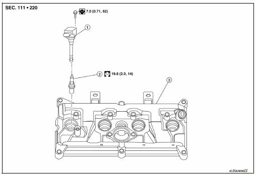
- Ignition coil
- Spark plug
- Rocker cover
Removal and Installation
REMOVAL
- Remove engine cover. Refer to EM-24, "Exploded View".
- Remove ignition coil. Refer to EM-46, "Exploded View".
- Remove spark plug using suitable tool.
(a) : 14 mm (0.55 in)
CAUTION:
Do not drop or shock spark plug.
INSTALLATION
Installation is in the reverse order of removal.
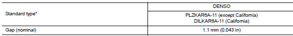
*: Always check with the Parts Department for the latest parts information.
CAUTION:
Always tighten the spark plug to specified torque to align the orientation of electrodes. The ground electrode of a genuine spark plug is positioned in the area of maximum ignitability by tightening to the specified torque. When replacing spark plugs, use genuine spark plugs of which the ground electrode is adjusted.
NOTE:
The ground electrode of the spark plug is positioned in the area of maximum ignitability to improve combustion efficiency in the cylinder, reduce CO2 (carbon dioxide) emission and improve fuel economy.
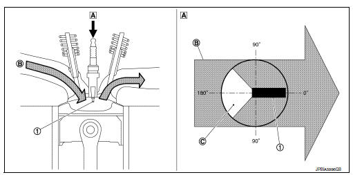
- Ground electrode of spark plug
- Top view
- Air-fuel mixture flow
- Poor ignitability region
Inspection
INSPECTION AFTER REMOVAL
Use the standard type spark plug for normal condition.
Spark plug (Standard type) : Refer to EM-118, "Spark Plug".
CAUTION:
- Do not drop or shock spark plug.
- Do not use a wire brush for cleaning.
- If plug tip is covered with carbon, spark plug cleaner may be used.
Cleaner air pressure : Less than 588 kPa (6 kg/cm2, 85 psi)
Cleaning time : Less than 20 seconds
- Spark plug gap adjustment is not required between replacement intervals.
- Measure spark plug gap. when it exceeds the limit, replace
spark plug even if it is with in the specified replacement mileage.
Refer to EM-118, "Spark Plug".

 Drive belt
Exploded View
Alternator
Drive belt auto-tensioner
Crankshaft pulley
A/C compressor
Water pump
Drive belt
Possible use range
New drive belt range
Indicator
Removal and ...
Other materials:
Readiness for inspection/maintenance (I/M) test
Due to legal requirements in some states and
Canadian Provinces, your vehicle may be required
to be in what is called the “ready condition”
for an Inspection/Maintenance (I/M) test of
the emission control system.
The vehicle is set to the “ready condition” when it
is driven through c ...
Precaution for Liquid Gasket
Removal of liquid gasket
After removing the bolts and nuts, separate the mating surface and
remove the old liquid gasket using tool.
Tool number : kv10111100 (j-37228)
Caution:
Do not damage the mating surfaces.
Tap the seal cutter to insert it (1).
In areas where the tool is diffic ...
Controls
Fan control dial
The fan control dial turns the fan on and off, and
controls fan speed.
Air flow control buttons
The air flow control buttons allow you to select
the air flow outlets.
MAX — Air flows from center and side
A/Cvents with maximum cooling.
— Air flows from center and side
v ...
