Nissan Sentra Service Manual: Ecu diagnosis information
Abs actuator and electric unit (control unit)
Reference Value
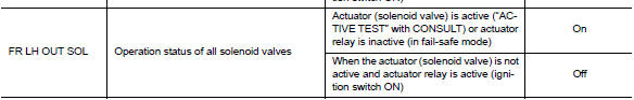
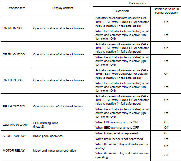
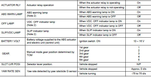
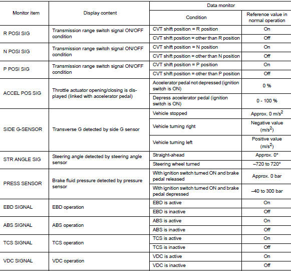
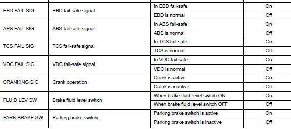
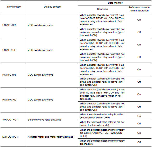
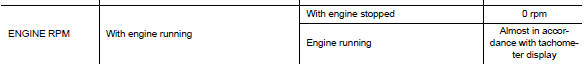
VALUES ON THE DIAGNOSIS TOOL
CAUTION:
The display shows the control unit calculation data, so a normal value might be displayed even in the event the output circuit (harness) is open or short-circuited.
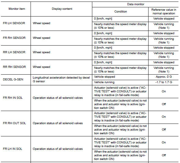
Note 1:
Confirm tire pressure is normal. Note 2
: On and off timing for warning lamps and indicator lamps.
-
Refer to BRC-22, "VDC/TCS/ABS : VDC Function".
-
Refer to BRC-24, "VDC/TCS/ABS : TCS Function".
-
Refer to BRC-26, "VDC/TCS/ABS : ABS Function".
-
Refer to BRC-27, "VDC/TCS/ABS : EBD Function".
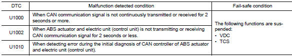
Fail-safe
VDC AND TCS FUNCTIONS
VDC warning lamp in combination meter turns ON when a malfunction occurs in system [ABS actuator and electric unit (control unit)]. The control is suspended for VDC and TCS functions. However, ABS and EBD functions operate normally.
ABS FUNCTION
ABS warning lamp and SLIP indicator lamp in combination meter turn ON when a malfunction occurs in system [ABS actuator and electric unit (control unit)]. The control is suspended for VDC, TCS and ABS functions.
However, EBD functions operate normally.
EBD FUNCTION
ABS warning lamp, brake warning lamp and SLIP indicator lamp in combination meter turn ON when a malfunction occurs in system [ABS actuator and electric unit (control unit)]. The control is suspended for VDC, TCS, ABS and EBD functions.
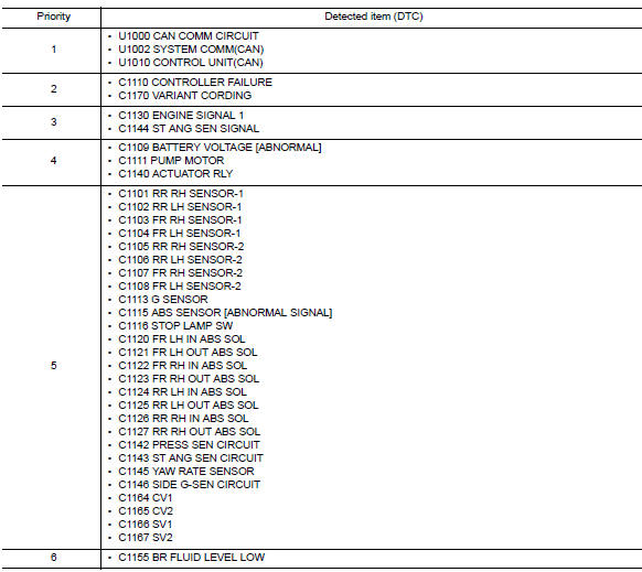
DTC Inspection Priority Chart
When multiple DTCs are displayed simultaneously, check each one using the following priority list.
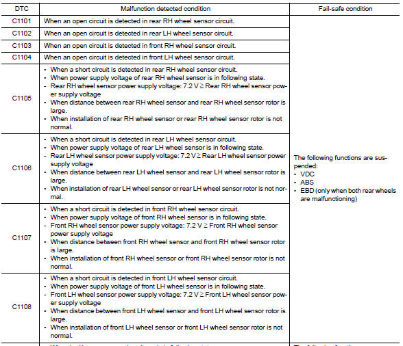
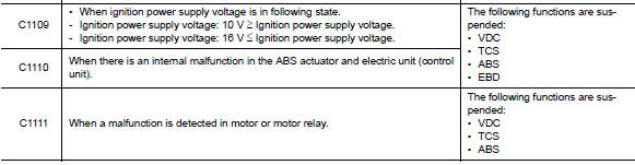
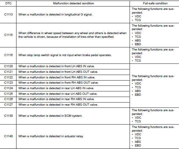
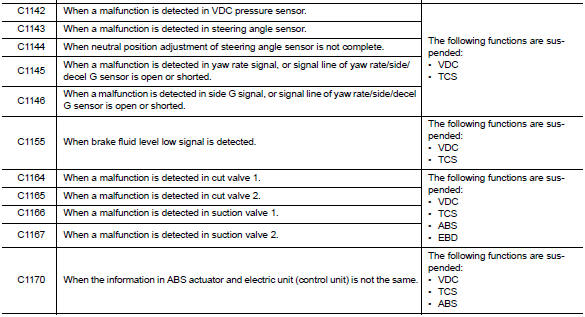
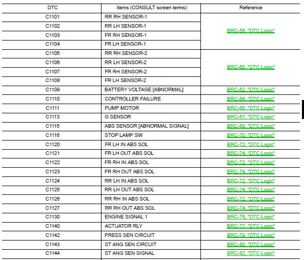
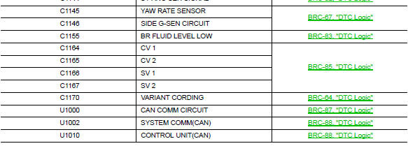
DTC Index
 Diagnosis system [abs actuator and electric unit (control
unit)]
Diagnosis system [abs actuator and electric unit (control
unit)]
CONSULT Function (ABS)
FUNCTION
CONSULT can display each diagnostic item using the following
direct diagnostic modes.
Direct Diagnostic Mode
Description
ECU identification
T ...
 Wiring diagram
Brake control system
Wiring Diagram
...
Other materials:
Battery current sensor
Exploded view
Battery current sensor
Current sensor harness connector
Removal and installation
Removal
Loosen the battery terminal nut and disconnect battery negative
terminal. Refer to PG-50, "Exploded
View".
Disconnect the harness connector from current sensor.
...
Wiring diagram
Rear window defogger system
Wiring diagram
...
Front disc brake
Exploded View
Cap
Bleeder valve
Cylinder body
Piston seal
Piston
Piston boot
Upper sliding pin
Lower sliding pin
Sliding pin boot
Bushing
Torque member
Apply brake fluid
Apply rubber grease
Disassembly and Assembly
DISASSEMBLY
Place a wooden block as shown, and ...
