Nissan Sentra B18 (2020-2025) Service Manual: Component Parts
Power Distribution System
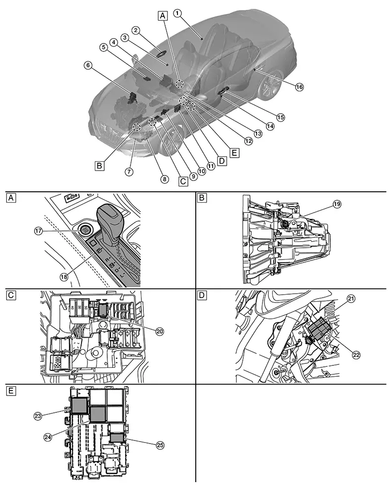
Component Parts Location
Component Parts Location
|
A. |
Front of center console |
B. |
M/T transmission (view with M/T transmission removed) |
C. |
Engine compartment LH |
|
D. |
Underneath instrument panel LH |
E. |
Fuse block (J/B) [view with fuse block (J/B) removed] |
||
|
No. |
Component |
Description |
|
|---|---|---|---|
|
1. |
Rear door switch RH |
Transmits the door switch signal to the BCM. Refer to Rear Door Switch for detailed component location. |
|
|
2. |
Front door request switch RH |
Transmits the door request switch signal to the Intelligent Key unit. Refer to Front Door Request Switch RH for detailed component location. |
|
|
3. |
Front door switch RH |
Transmits the door switch signal to the BCM. Refer to Front Door Switch for detailed component location. |
|
|
4. |
AV control unit |
Receives the auto ACC request signal from the BCM via CAN communication. Refer to AV Control Unit (with 7” color display) or AV Control Unit (with 8” color display) for detailed component location. |
|
|
5. |
Intelligent Key unit |
Receives the push-button ignition switch input and transmits the signal to the BCM and IPDM E/R via CAN communication. Refer to Intelligent Key Unit for detailed component location. |
|
|
6. |
ABS (Anti-lock Braking System) Actuator and Electric Unit (Control Unit) |
Transmits the Nissan Sentra vehicle speed signal to the BCM via CAN communication. Refer to ABS Actuator and Electric Unit (Control Unit) for detailed component location. |
|
|
7. |
CVT unit (with CVT) |
Transmission range switch |
Transmits the P (park) and N (neutral) position signals to the TCM. Refer to Transmission Range Switch for detailed component location. |
|
8. |
TCM (Transmission Control Module) (with CVT) |
Transmits the P (park) and N (neutral) position signals to the IPDM E/R via CAN communication. Refer to TCM for detailed component location. |
|
|
9. |
IPDM E/R (Intelligent Power Distribution Module Engine Room) |
Receives the ignition relay-1 (IPDM E/R) control signal and push-button ignition switch ON signal from the Intelligent Key unit via CAN communication, and controls the ignition relay-1 (built into IPDM E/R). Refer to System Description. |
|
|
10. |
Clutch master cylinder (clutch switch) (With M/T) |
Transmits the clutch switch (START) and clutch switch (END) signals to the BCM. |
|
|
11. |
BCM (Body Control Module) |
Refer to System Description. |
|
|
12. |
Combination meter |
Receives the ignition battery saver signal from the BCM via CAN communication. Refer to Combination Meter (type A) or Combination Meter (type B) for detailed component location. |
|
|
13. |
Combination switch |
Transmits the combination switch signal to the BCM. Refer to System Description. |
|
|
14. |
Front door switch LH |
Transmits the door switch signal to the BCM. Refer to Front Door Switch for detailed component location. |
|
|
15. |
Front door request switch LH |
Transmits the door request switch signal to the Intelligent Key unit. Refer to Front Door Request Switch LH for detailed component location. |
|
|
16. |
Rear door switch LH |
Transmits the door switch signal to the BCM. Refer to Rear Door Switch for detailed component location. |
|
|
17. |
Push-button ignition switch |
Refer to Push-Button Ignition Switch. |
|
|
18. |
CVT shift selector (detent switch) (with CVT) |
Transmits the detent switch signal to the BCM. Refer to Component Parts Location for detailed component location. |
|
|
19. |
Park/neutral position (PNP) switch (with M/T) |
Transmits the N (neutral) position signal to the IPDM E/R. Refer to Component Parts Location for detailed component location. |
|
|
20. |
Starter cut relay (in fuse, fusible link and relay box) |
The BCM controls the starter cut relay according to the request signal from the Intelligent Key unit and push-button ignition switch. |
|
|
21. |
Brake pedal position switch |
Detects that the brake pedal is depressed and transmits the signal to the BCM. Refer to Brake Pedal Position Switch (halogen headlamp) or Brake Pedal Position Switch (LED headlamp) for detailed component location. |
|
|
22. |
Stop lamp switch |
Detects that the brake pedal is depressed and transmits the signal to the BCM. Refer to Stop Lamp Switch (halogen headlamp) or Stop Lamp Switch (LED headlamp) for detailed component location. |
|
|
23. |
Accessory relay-1 [in fuse block (J/B)] |
|
|
|
24. |
Ignition relay-3 [in fuse block (J/B)] |
|
|
|
25. |
Ignition relay-2 [in fuse block (J/B)] |
|
|
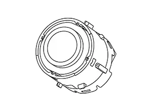
Push-Button Ignition Switch
Push-Button Ignition Switch
-
The push-button ignition switch is installed in center console finisher.
-
When the push-button ignition switch is pressed it transmits the status signal to the Intelligent Key unit.
Other materials:
P2808-00 Pressure Control Solenoid G
Dtc Description
DTC Description
DTC DETECTION LOGIC
DTC
CONSULT screen terms
(Trouble diagnosis
content)
DTC detection
conditi ...
B1036-16 Ignition Voltage
Dtc Description
DTC Description
DTC DETECTION LOGIC
DTC No.
CONSULT screen items
(Trouble diagnosis
content)
DTC Detection Condition
...
Trip computer
1. Vehicle speed
The vehicle speed screen shows the current speed of the Nissan Sentra as well
as the average vehicle speed calculated since the last reset.
Average vehicle speed:
Press the OK button on the steering wheel to open the drive computer Reset menu,
then follow the on-screen in ...