Nissan Sentra B18 (2020-2025) Service Manual: Charging System :: System Description
Component Parts. Charging System
Component Parts Location
Component Parts Location
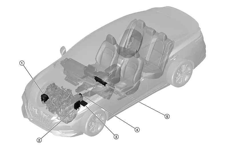
|
No. |
Component |
Function |
|---|---|---|
|
1. |
Generator (IC voltage regulator) |
IC voltage regulator controls the generator voltage based on the received signal. When there is no command signal, the generator performs the normal power generation according to the characteristic of the IC voltage regulator. Refer to Component Description. |
|
2. |
IPDM E/R (Intelligent Power Distribution Module Engine Room) |
The IPDM E/R sends the generator voltage request signal to the ECM via CAN communication. Refer to System Description. |
|
3. |
ECM (Engine Control Module) |
The ECM transmits the generator voltage request signal received from the IPDM E/R to the generator via LIN communication signal. Refer to Component Parts Location for detailed component location. |
|
4. |
Battery current sensor (with temperature sensor) |
The battery current sensor is installed to the battery negative cable. The sensor measures the charging/discharging current of the battery. Battery temperature sensor is integrated in battery current sensor. Refer to Component Description. |
|
5. |
Combination meter (Charge warning lamp) |
The IC regulator warning function activates to illuminate the charge warning lamp if any of the following symptoms occur while generator is operating:
Refer to Component Parts Location (Type A) or Component Parts Location (Type B) for detailed component location. |
Generator
Component Description
Component Description
-
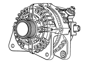
The generator is located at lower RH side of engine compartment.
-
The generator provides DC voltage to operate the Nissan Sentra vehicle's electrical system and to keep the battery charged.
Battery Current Sensor (with Battery Temperature Sensor)
Component Description
Component Description
-
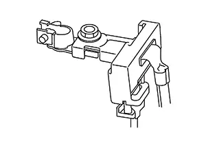
12V battery temperature sensor is integrated in 12V battery current sensor. Sensor measures temperature around 12V battery.
-
12V battery current sensor measures charging/discharging current of 12V battery and sends its signal to IPDM E/R.
Charging System. System Description. System Description
System Description
-
The generator includes a self-diagnosis function and transmits a diagnosis signal to the ECM via LIN communication when detecting a malfunction.
-
The generator provides DC voltage to operate the Nissan Sentra vehicle's electrical system and to keep the battery charged. The voltage output is controlled by the IC regulator.
SIGNAL TRANSMISSION FUNCTION LIST
|
Signal name |
Input |
Output |
Description |
|---|---|---|---|
|
Charge warning lamp signal |
ECM |
Combination meter (CAN) |
Transmits the charge warning lamp signal to the combination meter via CAN communication. |
|
Generator voltage request signal |
ECM |
Generator (IC regulator) (LIN) |
Transmits the generator voltage request signal to the generator via LIN communication. |
Power Generation Voltage Variable Control System. System Description. System Description
System Description
Power generation voltage variable control system has been adopted. By varying the voltage to the generator, engine load due to power generation of the generator is reduced and fuel consumption is decreased.
Note:
When any malfunction is detected in the power generation voltage variable control system, power generation is performed according to the characteristic of the IC regulator in the generator.
SIGNAL TRANSMISSION FUNCTION LIST
|
Signal name |
Input |
Output |
Description |
|---|---|---|---|
|
Power generation command value |
IPDM E/R |
ECM (CAN) |
Transmits the power generation command value to the ECM via CAN communication. |
Warning/indicator/chime List. Warning / Indicator / Chime List. Warning / Indicator / Chime List
Warning / Indicator / Chime List
|
Item |
Design |
Reference |
|---|---|---|
|
Charge warning lamp |
|
For layout, refer to Design (Type A) or Design (Type B). |

Other materials:
Horn. Precaution. Precautions. Precaution for Supplemental Restraint System (srs) "air Bag" and "seat Belt Pre-Tensioner"
Precautions. Precaution for Supplemental Restraint System (srs) "air Bag" and "seat Belt Pre-Tensioner"
Precaution for Supplemental Restraint System (srs) "air Bag" and "seat Belt Pre-Tensioner"
Precaution for Supplemental Restraint System (SRS) "AIR BAG" an ...
C1608-54 Control Unit
Dtc Description
DTC Description
DTC DETECTION LOGIC
DTC No.
CONSULT screen terms
(Trouble diagnosis content)
DTC detection condition
...
P0300 Misfire
Dtc Description
DTC Description
When a misfire occurs, engine speed will fluctuate. If the engine
speed fluctuates enough to cause the crankshaft position (CKP) sensor signal to
vary, ECM can determine that a misfire is occurring.
...