Nissan Sentra B18 (2020-2025) Service Manual: Camshaft Valve Clearance
Inspection and Adjustment
INSPECTION
Perform inspection as follows after removal, installation or replacement of camshaft or valve-related parts, or if there is unusual engine conditions regarding valve clearance.
Remove rocker cover. Refer to Removal and Installation.
Measure the valve clearance with the following procedure: Set No. 1 cylinder at TDC of its compression stroke.
-
Rotate crankshaft pulley (1) clockwise and align TDC mark [no paint (B)] to timing indicator (A) on front cover.
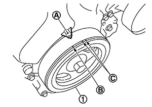
(C)
: White paint mark (Not use for service)
-
At the same time, check that both intake and exhaust cam noses of No. 1 cylinder face inside (
 )
as shown in the figure.
)
as shown in the figure.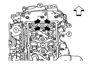
(1)
: Camshaft (INT)
(2)
: Camshaft (EXT)

: Engine front
-
If they do not face inside, rotate crankshaft pulley once more (360 degrees) and align as shown in the figure.
|
Valve clearance |
: Refer to Camshaft. |
-
By referring to the figure, measure the valve clearances at locations marked “×” as shown in the table below [locations indicated with black arrow (
)] with a suitable
tool.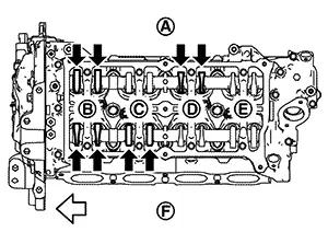
(A)
: Exhaust side
(B)
: No. 1 cylinder
(C)
: No. 2 cylinder
(D)
: No. 3 cylinder
(E)
: No. 4 cylinder
(F)
: Intake side
: Engine front
Measuring position
No. 1 CYL.
No. 2 CYL.
No. 3 CYL.
No. 4 CYL.
No. 1 cylinder at compression TDC
EXH
Ă—
Ă—
INT
Ă—
Ă—
-
Rotate crankshaft pulley (1) one revolution (360 degrees) and align TDC mark [no paint (B)] to timing indicator (A) on front cover.
(C)
: White paint mark (Not use for service)
-
By referring to the figure, measure the valve clearance at locations marked “×” as shown in the table below [locations indicated with black arrow (
)] with a suitable
tool.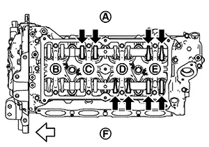
(A)
: Exhaust side
(B)
: No. 1 cylinder
(C)
: No. 2 cylinder
(D)
: No. 3 cylinder
(E)
: No. 4 cylinder
(F)
: Intake side
: Engine front
Measuring position
No. 1 CYL.
No. 2 CYL.
No. 3 CYL.
No. 4 CYL.
No. 4 cylinder at compression TDC
EXH
Ă—
Ă—
INT
Ă—
Ă—
If out of standard, perform adjustment. Refer to “ADJUSTMENT”.
ADJUSTMENT
-
Perform adjustment depending on selected head thickness of valve lifter.
Remove camshaft. Refer to Removal and Installation.
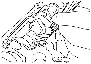
Remove valve lifters at the locations that are out of the standard.
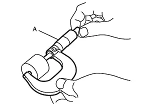
Measure the
center thickness of the removed valve lifters with a suitable tool
(A).
Use the equation below to calculate valve lifter thickness for replacement.
|
Valve lifter thickness calculation: |
t = t1 + (C1 – C2) |
||||
|
t |
= Valve lifter thickness to be replaced |
||||
|
t1 |
= Removed valve lifter thickness |
||||
|
C1 |
= Measured valve clearance |
||||
|
C2 |
= Standard valve clearance: |
||||
|
Intake |
: 0.28 mm (0.011 in) |
||||
|
Exhaust |
: 0.30 mm (0.012 in) |
||||
-
Thickness of new valve lifter (B) can be identified by stamp mark (A) on the reverse side (inside the cylinder).
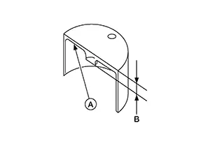
-
Stamp marks “302, 02FS, 02fs, 02Fb, 02fB" indicate 3.02 mm (0.1189 in) in thickness for intake valve lifters and "302, 02JS, 02js, 02JB, 02jb" indicate 3.02 mm (0.1189 in) in thickness for exhaust valve lifters.

Available thickness of valve lifter: 26 sizes range 3.00 to 3.50 mm (0.1181 to 0.1378 in) in steps of 0.02 mm (0.0008 in) (when manufactured at factory). Refer to Camshaft.
Install the selected valve lifter.
Install camshaft. Refer to Removal and Installation.
Install timing chain and related parts. Refer to Removal and Installation.
Manually rotate crankshaft pulley a few rotations.
Check that the valve clearances is within the standard. Refer to “INSPECTION”.
Installation of the remaining parts is in the reverse order of removal.
Warm up the engine, and check for unusual noise and vibration.
 Basic Inspection
...
 Compression Pressure
Inspection
Inspection
Warm up
engine to full operating temperature. Stop engine.
Release the
fuel pressure. Refer to Work Procedure.
Remove the
fuel pump fuse from IPDM E/R t ...
Other materials:
Interior room lamp
Removal and installation
Removal
Insert a suitable tool into the gap between the headlining and the
interior room lamp and release the interior
room lamp.
Disconnect the harness connector from the interior room lamp.
Installation
Installation is in the reverse order of removal.
Bul ...
Confirmation Procedure
Confirmation Procedure
PRECONDITIONING
If “Confirmation Procedure” has been
previously conducted, always place the ignition switch OFF and wait
at least 10 seconds before conducting the next test.
>&g ...
Contents
Contents
THE CONTENTS are listed on the first page
of each section.
THE TITLE is indicated on the upper
portion of each page and shows the part or system.
THE PAGE NUMBER of each section consists
of two or three letters which desi ...
