Nissan Sentra Service Manual: Brake booster
Exploded View
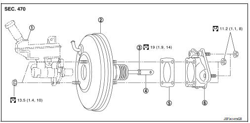
- Master cylinder assembly
- Brake booster
- Lock nut
- Clevis
- Gasket
- Spacer
Removal and installation
REMOVAL
- Remove cowl top and cowl top extension. Refer to EXT-26, "Removal and Installation".
- Remove air duct and air cleaner case. Refer to EM-25, "Removal and Installation".
- Remove brake master cylinder assembly. Refer to BR-32, "Removal and Installation".
- Remove vacuum hose from brake booster. Refer to BR-36, "Removal and Installation".
- Remove the instrument lower panel LH. Refer to IP-21, "Removal and Installation".
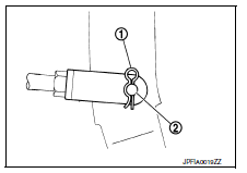
- Remove snap pin (1) and clevis pin (2). Refer to BR-22, "Exploded View".
- Remove nuts on brake booster and brake pedal assembly.
CAUTION:
Secure the brake booster to avoid damage to components.
- Remove brake booster and spacer.
CAUTION:
Do not deform or bend brake pipes.
NOTE:
If removing brake booster is difficult, remove clevis from brake booster.
- Remove vacuum pipe from brake booster.
- Remove spacer from brake booster.
INSTALLATION
Installation is in the reverse order of removal.
CAUTION:
- Be careful not to damage brake booster stud bolt threads. If brake booster is tilted during installation, the dash panel may damage the threads.
- Do not deform or bend the brake tubes when installing the brake booster.
- Always use a gasket between the brake booster and the spacer.
- Do not reuse the clevis pin.
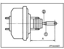
- Loosen the lock nut (1) and adjust the input rod (2) to the specified length (A). Tighten the lock nut to the specified torque.
Length (A) : Refer to BR-55, "Brake Booster".
- Perform the air bleeding. Refer to BR-17, "Bleeding Brake System".
- Check each item of brake pedal. Adjust it if the measurement value is not the standard. Refer to BR-11, "Inspection".
 Brake master cylinder
Exploded View
Reservoir cap
Oil strainer
Reservoir tank
Cylinder body
Pin
O-ring
Grommet
Apply brake fluid
PBC (Poly Butyl Cuprysil)
grease or
silicone-based grease
Remo ...
 Vacuum lines
Exploded View
Clamp
Vacuum hose (built-in check valve)
Vacuum piping
Vacuum hose
To intake manifold side
Paint mark
Stamp indicating engine direction
To brake booster
Remo ...
Other materials:
Diagnosis system (bcm) (with intelligent key system)
Common item
Common item : consult function (bcm - common item)
Application item
Consult performs the following functions via can communication with bcm.
Direct diagnostic mode
Description
ECU identification
The BCM part number is displayed.
Self diagnostic result
...
Symptom diagnosis
Engine does not start when intelligent key is inside of vehicle
Description
Engine does not start when push-button ignition switch is pressed while
carrying intelligent key.
Note:
Check that vehicle is under the condition shown in “conditions of
vehicle” before starting diagnos ...
Transmitter
Exploded View
Transmitter (tire pressure sensor)
O-ring
Valve stem nut
Valve core
Valve cap
Valve stem assembly
Parts that are replaced as a set
when the tire is replaced.
Removal and Installation
REMOVAL
Remove road wheel and tire assembly using power tool.
Remove val ...
