Nissan Sentra B18 (2020-2025) Service Manual: B2e08 Microphone
Dtc Description
DTC Description
DTC DETECTION LOGIC
|
DTC No. |
CONSULT screen terms (Trouble diagnosis content) |
DTC detection condition |
||
|---|---|---|---|---|
|
B2E08ŌĆō01 |
Microphone (Microphone) |
1 |
Diagnosis condition |
When ignition switch is ON. |
|
Signal (terminal) |
Microphone signal |
|||
|
Threshold |
7.2 V or more |
|||
|
Diagnosis delay time |
1 second or more |
|||
|
2 |
Diagnosis condition |
When ignition switch is ON. |
||
|
Signal (terminal) |
Microphone signal |
|||
|
Threshold |
0.2 V or less |
|||
|
Diagnosis delay time |
1 second or more |
|||
POSSIBLE CAUSE
-
Microphone signal circuit short to power supply
-
Microphone signal circuit short to ground
-
Microphone
FAIL-SAFE
Microphone does not operate
Confirmation Procedure
Confirmation Procedure
-
PERFORM DTC CONFIRMATION PROCEDURE
-
 CONSULT
-
Ignition switch ON.
-
Ignition switch OFF and wait at least 30 seconds.
-
Ignition switch ON and wait at least 30 seconds or more.
-
Select ŌĆ£Self Diagnostic ResultŌĆØ mode of ŌĆ£IVCŌĆØ.
-
Check DTC.
-
Is DTC B2E08ŌĆō01 detected?
YES>>Proceed to DTC Diagnosis Procedure.
NO>>To check malfunction symptom before repair: Refer to Intermittent Incident.
NO>>Confirmation after repair: Inspection End.
-
Dtc Diagnosis Procedure
DTC Diagnosis Procedure
-
CHECK MICROPHONE SIGNAL CIRCUIT AND MICROPHONE VCC CIRCUIT CONTINUITY
-
-
Ignition switch OFF.
-
Disconnect TCU connector and microphone connector.
-
Check continuity between TCU connector and microphone connector.
TCU
Microphone
Continuity
Connector
Terminal
Connector
Terminal
M160
17
R17
1
Yes
18
4
-
Check the continuity between TCU connector and ground.
TCU
ŌĆö
Continuity
Connector
Terminal
M160
17
Ground
No
18
-
Is the inspection result normal?
YES >>GO TO 2.
NO >>Repair or replace harness or connectors.
-
-
CHECK MICROPHONE VCC VOLTAGE
-
-
Connect TCU connector and microphone connector.
-
Ignition switch ON.
-
Check voltage between TCU connector and ground.
(+)
(ŌłÆ)
Voltage
(Approx.)
TCU
Connector
Terminal
M160
18
Ground
5 V
-
Is the inspection result normal?
YES >>GO TO 3.
NO >>Replace TCU. Refer to Removal and Installation.
-
-
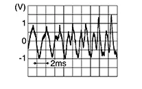
CHECK MICROPHONE SIGNAL
-
Check signal between TCU connector and ground.
(+)
(ŌłÆ)
Condition
Reference value
TCU
Connector
Terminal
M160
17
Ground
Speak into microphone.
Is the inspection result normal?
YES >>Replace TCU. Refer to Removal and Installation.
NO >>Replace microphone. Refer to Removal and Installation.
-
Other materials:
U2141 Mac Comm Error (tcm)
Dtc Description
DTC Description
DTC DETECTION LOGIC
DTC No.
CONSULT screen terms
(Trouble diagnosis
content)
DTC detection condition
...
System (power Door Lock System). System Description
System Description
System Description
INPUT SIGNAL AND OUTPUT SIGNAL
Signal name
Input
Output
Description
...
Warning/Indicator lights (other)
For additional details about warning and indicator functions in the Nissan Sentra,
refer to the sections titled "Vehicle information display 4.2 inch (11 cm) Type
A" or "Vehicle information display 7 inch (18 cm) Type B", depending on the equipment
installed in your vehicle ...