Nissan Sentra Service Manual: B00A0 OCS System
Description
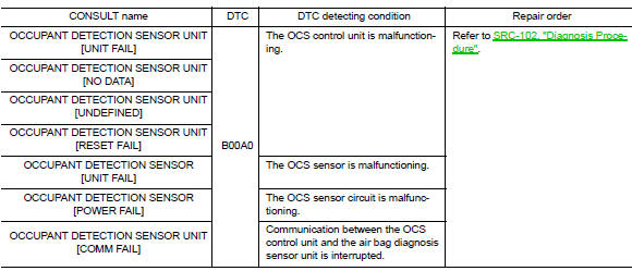
DTC B00A0 OCCUPANT CLASSIFICATION SYSTEM (OCS)
The OCS control unit is wired to the air bag diagnosis sensor unit. The air bag diagnosis sensor unit will monitor the OCS for failures and interruptions in communication between the OCS control unit and the air bag diagnosis sensor unit.
PART LOCATION
Refer to SRC-5, "Component Parts Location".
DTC Logic
DTC DETECTION LOGIC
With CONSULT
DTC CONFIRMATION PROCEDURE (With CONSULT)
1.CHECK SELF-DIAG RESULT
- Turn ignition switch ON.
- Check for DTC using CONSULT.
Is the DTC detected? YES (Current DTC)>>Refer to SRC-102, "Diagnosis Procedure".
YES (Past DTC)>>GO TO 2.
NO >> Inspection End.
2.ERASE SELF-DIAG RESULT
Erase the DTC using CONSULT.
Can the DTC be erased? YES >> Inspection End.
NO >> Refer to SRC-102, "Diagnosis Procedure".
DTC CONFIRMATION PROCEDURE (Without CONSULT)
1.CHECK SELF-DIAG RESULT
- Turn ignition switch ON.
- Check the air bag warning lamp status. Refer to SRC-17, "Trouble Diagnosis without CONSULT".
NOTE:
SRS will not enter diagnosis mode if no malfunction is detected in user mode.
Is the DTC detected? YES >> Refer to SRC-102, "Diagnosis Procedure".
NO >> Inspection End.
Diagnosis Procedure
1.HARNESS CONNECTOR
Visually inspect all applicable harness connectors for the following:
- Visible damage to connector or terminal
- Loose terminal
- Poor connection
NOTE:
All harness connectors should be inspected from the air bag diagnosis unit to the end component (including any in-line connectors).
Is the inspection result normal? YES >> GO TO 2.
NO >> Perform one of the following repairs:
- Visible damage: Replace the harness.
- Loose terminal: Secure the terminal
- Poor connection: Secure the connection
2.CONFIRM DTC
- Reconnect all harness connectors.
- Turn ignition switch ON
- Check for DTC using CONSULT.
Is DTC still current? YES >> GO TO 3.
NO >> Refer to GI-39, "Intermittent Incident".
3.WIRING HARNESS
Check the wiring harness for visible damage.
NOTE
The entire wiring harness should be inspected from the air bag diagnosis sensor unit to the end component (including any in-line connectors).
Is the inspection result normal? YES >> GO TO 4.
NO >> Replace the harness.
4.CONFIRM DTC
- Reconnect all harness connectors.
- Turn ignition switch ON.
- Check for DTC using CONSULT.
Is DTC still current? YES >> GO TO 5.
NO >> Refer to GI-39, "Intermittent Incident".
5.REPLACE OCCUPANT CLASSIFICATION SYSTEM CONTROL UNIT
- Replace the occupant classification control unit. Refer to SR-30, "Removal and Installation".
- Turn ignition switch ON
- Check for DTC using CONSULT.
Is DTC still current? YES >> GO TO 6.
NO >> Clear DTC. Inspection End.
6.AIR BAG DIAGNOSIS SENSOR UNIT
- Replace the air bag diagnosis sensor unit. Refer to SR-28, "Removal and Installation".
- Turn ignition switch ON.
- Check for DTC using CONSULT.
Is DTC still current? YES >> GO TO 7.
NO >> Clear DTC. Inspection End.
7.RELATED HARNESS
Replace the related harness.
>> END
 B14XX Air bag diagnosis sensor unit
Description
DTC B14XX AIR BAG DIAGNOSIS SENSOR UNIT
The air bag diagnosis sensor unit will run self diagnostics when the ignition
switch is turned ON. It has the
potential to set many diagnostic ...
 B00D5 Passenger air bag OFF Indicator
Description
DTC B00D5 FRONT PASSENGER AIR BAG OFF INDICATOR
The front passenger air bag off indicator is wired to the air bag diagnosis
sensor unit. The air bag diagnosis
sensor unit monitors th ...
Other materials:
Periodic maintenance
CVT FLUID
Inspection
FLUID LEAKAGE
Check transaxle surrounding area (oil seal and plug etc.) for fluid
leakage.
If anything is found, repair or replace damaged parts and adjust
CVT fluid level. Refer to TM-251, "Adjustment".
Replacement
CVT fluid : Refer to TM-288, & ...
Front wiper does not operate
Description
The front wiper does not operate under any operation conditions
Diagnosis procedure
Regarding wiring diagram information, refer to ww-24, "wiring diagram - with
intelligent key" or ww-29,
"wiring diagram - without intelligent key".
1. Check wiper relay operatio ...
Power steering
WARNING
If the engine is not running or is turned
off while driving, the power assist for
the steering will not work. Steering will
be harder to operate.
When the power steering warning light
illuminates with the engine running,
there will be no power assist for th ...
