Nissan Sentra B18 (2020-2025) Service Manual: Accessory Relay-1
Diagnosis Procedure
-
CHECK ACCESSORY RELAY-1 POWER
-
-
Disconnect accessory relay-1 connector.
-
Check voltage between accessory relay-1 harness connector and ground.
Accessory relay-1
—
Voltage
(Approx.)
Connector
Terminal
J-5
2
Ground
Battery voltage
5
-
Is the inspection result normal?
YES >>GO TO 2.
NO >>Repair or replace harness or connectors.
-
-
CHECK ACCESSORY RELAY-1 CONTROL SIGNAL VOLTAGE
-
-
Connect accessory relay-1 connector.
-
Check voltage between BCM harness connector and ground.
+
—
Condition
Voltage
(Approx.)
BCM
Connector
Terminal
M84
34
Ground
Ignition switch
OFF
Battery voltage
ON
0 V
-
Is the inspection result normal?
YES >>GO TO 4
NO >>GO TO 3.
-
-
CHECK ACCESSORY RELAY-1 CONTROL SIGNAL CIRCUIT
-
-
Ignition switch OFF.
-
Disconnect BCM connector and accessory relay-1 connector.
-
Check continuity between BCM harness connector and accessory relay-1 harness connector.
BCM
Accessory relay-1
Continuity
Connector
Terminal
Connector
Terminal
M84
34
J-5
1
Yes
-
Check continuity between BCM harness connector and ground.
BCM
Ground
Continuity
Connector
Terminal
M84
34
No
-
Is the inspection result normal?
YES >>Replace BCM. Refer to Removal and Installation.
NO >>Repair or replace harness or connectors.
-
-
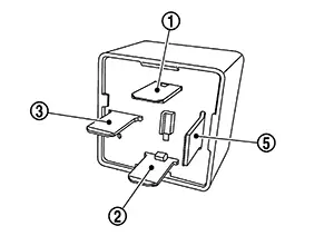
CHECK ACCESSORY RELAY-1
-
Check accessory relay-1. Refer to Component Inspection.
Is the inspection result normal?
YES >>Refer to Intermittent Incident.
NO >>Replace accessory relay-1.
-
Component Inspection
-
CHECK ACCESSORY RELAY-1
-
-
Ignition switch OFF.
-
Disconnect accessory relay-1 connector.
-
Check continuity between accessory relay-1 terminals.
Accessory relay-1
Condition
Continuity
Terminals


12 V direct current supply between terminals
 and
and  .
.Yes
No current supply
No
-
Is the inspection result normal?
YES >>Inspection End.
NO >>Replace accessory relay-1.
-
 Push-Button Ignition Switch Circuit
Component Function Check
Component Function
Check
CHECK FUNCTION
CONSULT
Ignition switch ON
...
Other materials:
Diagnosis Procedure
Diagnosis Procedure
CHECK INTELLIGENT KEY SYSTEM SYMPTOM
TABLE
Check Intelligent Key system symptom table.
Refer to Diagnosis Procedure.
>>
GO TO
2.
CHECK INTELLIGENT KEY BATTER ...
Removal and Installation
Removal and Installation
REMOVAL
CAUTION:
Be sure to perform “ADDITIONAL
SERVICE WHEN REPLACING INTELLIGENT KEY UNIT” when replacing
Intelligent Key unit. Refer to Work Procedure.
Remove
instrument panel assembly. Refer to Removal and Installation.
Disconn ...
Diagnosis system (BCM)
Common item
Common item : consult function (bcm - common item)
Application item
Consult performs the following functions via can communication with bcm.
System application
Bcm can perform the following functions.
Intelligent key
Intelligent key : consult function (bcm - intelligent ke ...
