Nissan Sentra B18 (2020-2025) Service Manual: Dtc/circuit Diagnosis
B2fac-12 Accessory Relay
Dtc Description
DTC Description
DTC DETECTION LOGIC
|
DTC No. |
CONSULT screen items (Trouble diagnosis content) |
DTC detection condition |
|
|---|---|---|---|
|
B2FAC-12 |
Accessory relay (Accessory relay) |
Diagnosis condition |
When ignition switch is ON |
|
Signal (terminal) |
Accessory relay-1 control signal (terminal #34) |
||
|
Threshold |
16 V or more |
||
|
Diagnosis delay time |
1 second or more |
||
POSSIBLE CAUSE
-
Harness or connectors (accessory relay-1 control signal circuit is shorted to battery)
-
Accessory relay-1
-
BCM
FAIL-SAFE
—
Dtc Confirmation Procedure
DTC Confirmation Procedure
-
PERFORM DTC CONFIRMATION PROCEDURE
-
 CONSULT
-
Ignition switch ON.
-
Ignition switch OFF and wait for 1 minute with the front door LH opened.
-
Ignition switch ON.
-
Select “Self Diagnostic Result� mode of “BCM�.
-
Is DTC detected?
YES>>Refer to DTC Diagnosis Procedure.
NO>>To check malfunction symptom before repair: Refer to Intermittent Incident.
NO>>Confirmation after repair: Inspection End.
-
Dtc Diagnosis Procedure
DTC Diagnosis Procedure
-
CHECK ACCESSORY RELAY-1 CONTROL SIGNAL CIRCUIT (SHORT TO BATTERY)
-
-
Ignition switch OFF.
-
Disconnect accessory relay-1 connector and BCM connector.
-
Check voltage between BCM harness connector and ground.
+
-
Voltage
(Approx.)
BCM
Connector
Terminal
M84
34
Ground
0 V
-
Is the inspection result normal?
YES >>GO TO 2.
NO >>Repair or replace harness
-
-
CHECK ACCESSORY RELAY-1
-
Check accessory relay-1. Refer to Component Inspection.
Is the inspection result normal?
YES>>Replace BCM. Refer to Removal and Installation.
NO>>Replace accessory relay-1.
-
B2fac-14 Accessory Relay
Dtc Description
DTC Description
DTC DETECTION LOGIC
|
DTC No. |
CONSULT screen items (Trouble diagnosis content) |
DTC detection condition |
|
|---|---|---|---|
|
B2FAC-14 |
Accessory relay (Accessory relay) |
Diagnosis condition |
When ignition switch is OFF (not auto ACC status) |
|
Signal (terminal) |
Accessory relay-1 control signal (terminal #34) |
||
|
Threshold |
0 V |
||
|
Diagnosis delay time |
1 second or more |
||
POSSIBLE CAUSE
-
Harness or connectors (accessory relay-1 control signal circuit is shorted to ground or open)
-
Accessory relay-1
-
BCM
FAIL-SAFE
—
Dtc Confirmation Procedure
DTC Confirmation Procedure
-
PERFORM DTC CONFIRMATION PROCEDURE
-
CONSULT
-
Ignition switch ON.
-
Ignition switch OFF and wait for 1 minute with the front door LH opened.
-
Ignition switch ON.
-
Select “Self Diagnostic Result� mode of “BCM�.
-
Is DTC detected?
YES>>Refer to DTC Diagnosis Procedure.
NO>>To check malfunction symptom before repair: Refer to Intermittent Incident.
NO>>Confirmation after repair: Inspection End.
-
Dtc Diagnosis Procedure
DTC Diagnosis Procedure
-
CHECK ACCESSORY RELAY-1 CONTROL SIGNAL VOLTAGE
-
-
Ignition switch OFF.
-
Disconnect BCM connector.
-
Check voltage between BCM harness connector and ground.
+
-
Voltage
(Approx.)
BCM
Connector
Terminal
M84
34
Ground
Battery voltage
-
Is the inspection result normal?
YES >>Replace BCM. Refer to Removal and Installation.
NO >>GO TO 2.
-
-
CHECK ACCESSORY RELAY-1 CONTROL SIGNAL CIRCUIT (OPEN)
-
-
Disconnect accessory relay-1 connector.
-
Check continuity between BCM harness connector and accessory relay-1 harness connector.
BCM
Accessory relay-1
Continuity
Connector
Terminal
Connector
Terminal
M84
34
J-5
1
Yes
-
Is the inspection result normal?
YES >>GO TO 3.
NO >>Repair or replace harness.
-
-
CHECK ACCESSORY RELAY-1 CONTROL SIGNAL CIRCUIT (SHORT TO GROUND)
-
Check continuity between BCM harness connector and ground.
BCM
—
Continuity
Connector
Terminal
M84
34
Ground
No
Is the inspection result normal?
YES >>GO TO 4.
NO >>Repair or replace harness.
-
-
CHECK ACCESSORY RELAY-1
-
Check accessory relay-1. Refer to Component Inspection.
Is the inspection result normal?
YES >>Inspection End.
NO >>Replace accessory relay-1.
-
Push-Button Ignition Switch Circuit
Component Function Check
Component Function Check
-
CHECK FUNCTION
-
CONSULT
-
Ignition switch ON
-
Select “Push SW� in “Data Monitor� mode of “HANDS FREE MODULE�.
-
Check the push-button ignition switch signal under the following conditions:
Test item
Condition
Status
Push SW
Push-button ignition switch is pressed
On
Push-button ignition switch is not pressed
Off
-
Is the indication normal?
YES>>Push-button ignition switch circuit is normal.
NO>>Refer to Diagnosis Procedure.
-
Diagnosis Procedure
Diagnosis Procedure
-
CHECK PUSH-BUTTON IGNITION SWITCH SIGNAL OUTPUT VOLTAGE
-
-
Ignition switch OFF.
-
Disconnect push-button ignition switch connector.
-
Check voltage between push-button ignition switch harness connector and ground.
+
-
Voltage
(Approx.)
Push-button ignition switch
Connector
Terminal
M25
8
Ground
Battery voltage
-
Is the inspection result normal?
YES >>GO TO 4.
NO >>GO TO 2.
-
-
CHECK PUSH-BUTTON IGNITION SWITCH SIGNAL CIRCUIT (OPEN)
-
-
Disconnect Intelligent Key unit connector.
-
Check continuity between push-button ignition switch harness connector and Intelligent Key unit harness connector.
Push-button ignition switch
Intelligent Key unit
Continuity
Connector
Terminal
Connector
Terminal
M25
8
M155
9
Yes
-
Is the inspection result normal?
YES >>GO TO 3.
NO >>Repair the harness or connector.
-
-
CHECK PUSH-BUTTON IGNITION SWITCH SIGNAL CIRCUIT (SHORT TO GROUND)
-
Check continuity between push-button ignition switch harness connector and ground.
Push-button ignition switch
—
Continuity
Connector
Terminal
M25
8
Ground
No
Is the inspection result normal?
YES >>Replace Intelligent Key unit. Refer to Removal and Installation.
NO >>Repair the harness or connector.
-
-
CHECK PUSH-BUTTON IGNITION SWITCH GROUND CIRCUIT
-
Check continuity between push-button ignition switch harness connector and ground.
Push-button ignition switch
—
Continuity
Connector
Terminal
M25
4
Ground
Yes
Is the inspection result normal?
YES >>GO TO 5.
NO >>Repair the harness or connector.
-
-
CHECK PUSH-BUTTON IGNITION SWITCH
-
Check push-button ignition switch. Refer to Component Inspection.
Is the inspection result normal?
YES >>Inspection End.
NO >>Replace push-button ignition switch. Refer to Removal and Installation.
-
Component Inspection
Component Inspection
-
CHECK PUSH-BUTTON IGNITION SWITCH
-
-
Ignition switch OFF.
-
Disconnect push-button ignition switch connector.
-
Check continuity between push-button ignition switch terminals.
Push-button ignition switch
Condition
Continuity
Terminals
4
8
Pressed
Yes
Not pressed
No
-
Is the inspection result normal?
YES>>Inspection End.
NO>>Replace push-button ignition switch. Refer to Removal and Installation.
-
Accessory Relay-1
Diagnosis Procedure
Diagnosis Procedure
-
CHECK ACCESSORY RELAY-1 POWER
-
-
Disconnect accessory relay-1 connector.
-
Check voltage between accessory relay-1 harness connector and ground.
Accessory relay-1
—
Voltage
(Approx.)
Connector
Terminal
J-5
2
Ground
Battery voltage
5
-
Is the inspection result normal?
YES >>GO TO 2.
NO >>Repair or replace harness or connectors.
-
-
CHECK ACCESSORY RELAY-1 CONTROL SIGNAL VOLTAGE
-
-
Connect accessory relay-1 connector.
-
Check voltage between BCM harness connector and ground.
+
—
Condition
Voltage
(Approx.)
BCM
Connector
Terminal
M84
34
Ground
Ignition switch
OFF
Battery voltage
ON
0 V
-
Is the inspection result normal?
YES >>GO TO 4
NO >>GO TO 3.
-
-
CHECK ACCESSORY RELAY-1 CONTROL SIGNAL CIRCUIT
-
-
Ignition switch OFF.
-
Disconnect BCM connector and accessory relay-1 connector.
-
Check continuity between BCM harness connector and accessory relay-1 harness connector.
BCM
Accessory relay-1
Continuity
Connector
Terminal
Connector
Terminal
M84
34
J-5
1
Yes
-
Check continuity between BCM harness connector and ground.
BCM
Ground
Continuity
Connector
Terminal
M84
34
No
-
Is the inspection result normal?
YES >>Replace BCM. Refer to Removal and Installation.
NO >>Repair or replace harness or connectors.
-
-
CHECK ACCESSORY RELAY-1
-
Check accessory relay-1. Refer to Component Inspection.
Is the inspection result normal?
YES >>Refer to Intermittent Incident.
NO >>Replace accessory relay-1.
-
Component Inspection
Component Inspection
-
CHECK ACCESSORY RELAY-1
-
-
Ignition switch OFF.
-
Disconnect accessory relay-1 connector.
-
Check continuity between accessory relay-1 terminals.
Accessory relay-1
Condition
Continuity
Terminals


12 V direct current supply between terminals
 and
and  .
.Yes
No current supply
No
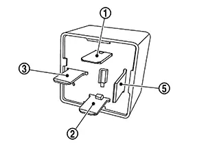
-
Is the inspection result normal?
YES >>Inspection End.
NO >>Replace accessory relay-1.
-
Power Supply and Ground Circuit
Ipdm E/r (intelligent Power Distribution Module Engine Room)
Diagnosis Procedure
Diagnosis Procedure
-
CHECK FUSE AND FUSIBLE LINKS
-
Check that the following IPDM E/R fuse or fusible links are not blown:
Terminal
Signal name
Fuse and fusible link No.
Capacity
1
Battery power supply
D
80 A
2
E
80 A
81
B
300 A
70
40 A
Is the fuse or fusible link blown?
YES >>Replace the blown fuse or fusible link after repairing the affected circuit.
NO >>GO TO 2.
-
-
CHECK POWER SUPPLY CIRCUIT
-
-
Ignition switch OFF.
-
Disconnect IPDM E/R connectors.
-
Check voltage between IPDM E/R harness connectors and ground.
IPDM E/R
—
Voltage
(Approx.)
Connector
Terminal
E42
1
Ground
Battery voltage
2
F97
81
-
Is the inspection result normal?
YES >>GO TO 3.
NO >>Repair harness or connectors.
-
-
CHECK GROUND CIRCUIT
-
-
Disconnect IPDM E/R connectors.
-
Check continuity between IPDM E/R harness connectors and ground.
IPDM E/R
—
Continuity
Connector
Terminal
E47
12
Ground
Yes
E43
31
E45
47
-
Is the inspection result normal?
YES>>Inspection End.
NO>>Repair harness or connectors.
-
Other materials:
Fuel Injector
Component Function Check
Component Function Check
INSPECTION START
Turn ignition switch to START.
Are any cylinders ignited?
YES >>
GO TO
2.
NO >>
Refer to Diagnosis Procedure.
CHECK FUEL INJECTOR FUNCTION
...
Basic Inspection
Additional Service When Replacing Adas Control Unit 2
Description
Description
Always perform the ADAS control unit 2 configuration after
replacing the ADAS control unit 2.
Work Procedure
Work Procedure
ADAS CONTROL UNIT 2 CONFIGURATION
CONSULT
Perform the ADA ...
U215b Can Comm Err (ipdm E/r)
Dtc Description
DTC Description
DTC DETECTION LOGIC
DTC No.
CONSULT screen terms
(Trouble diagnosis
content)
DTC detection condition
...